Serial system for blowing antifuses

a technology of anti-fuses and serial systems, which is applied in the direction of electronic/solid-state device details, digital storage, instruments, etc., can solve the problems of complex routing, slow program execution of parallel schemes, and substantial complexity of parallel schemes

Active Publication Date: 2008-10-16
MICRON TECH INC
View PDF12 Cites 1 Cited by
  • Summary
  • Abstract
  • Description
  • Claims
  • Application Information

AI Technical Summary

Problems solved by technology

As the number of antifuses in a device increases, this parallel scheme can be slow to program and wasteful of chip area.
In addition, complex routing may be required to provide access to the antifuses.
For example, in a memory device (e.g., DRAM) having large numbers of rows and columns in its memory array, the parallel scheme can substantially complicate the design of the device.
Such a fixed blowing time can be redundant or insufficient depending on the antifuses being blown.
If it is redundant, it can result in a waste of time and current resources to blow antifuses.
On the other hand, if it is insufficient, a desired electrical path may not be established.

Method used


Image

  • Serial system for blowing antifuses
  • Serial system for blowing antifuses
  • Serial system for blowing antifuses

Examples


Embodiment Construction

Serial System for Blowing Antifuses

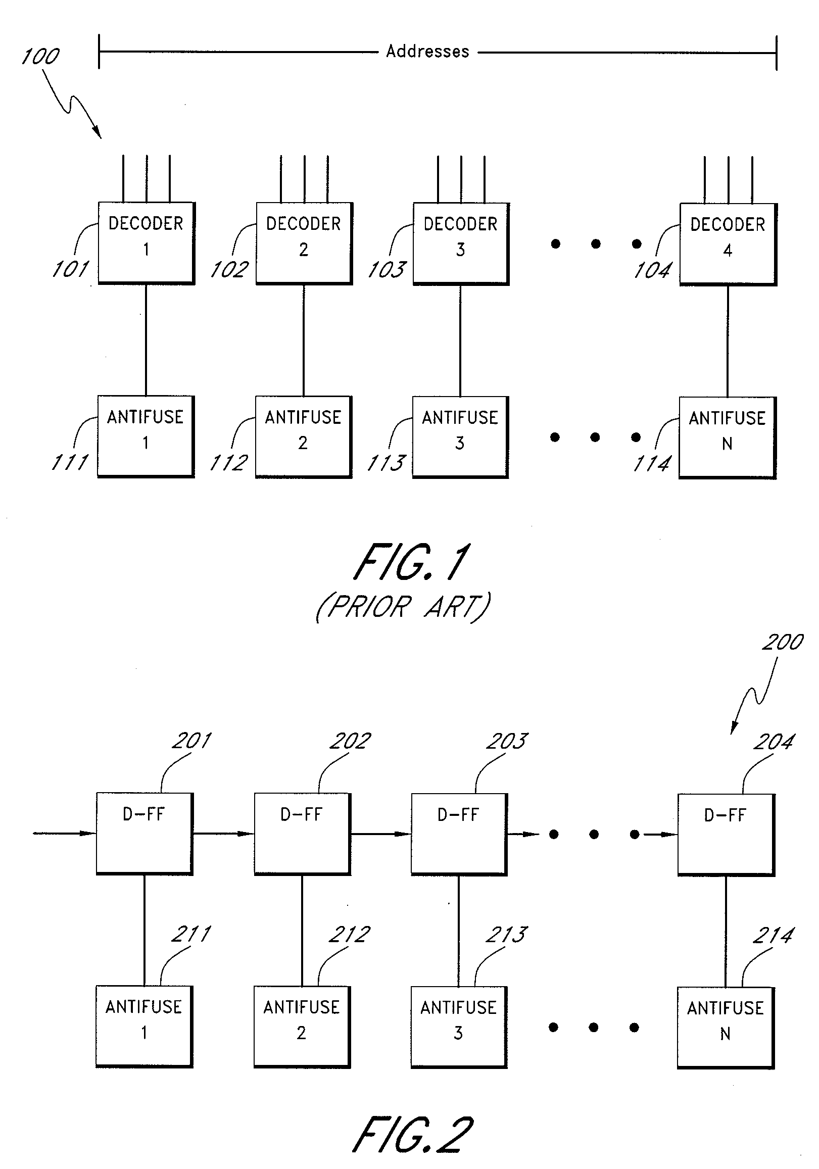
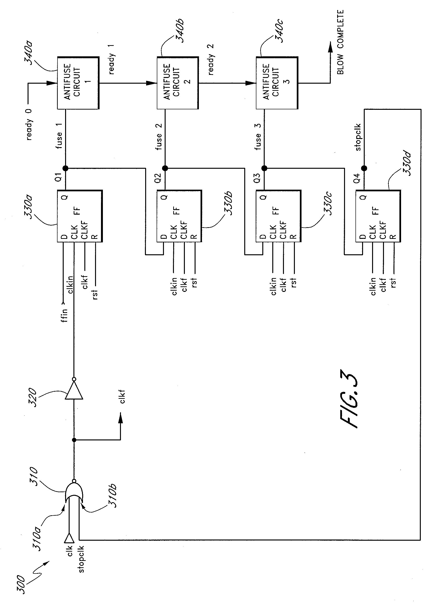
[0018]In one embodiment, a serial antifuse system is provided to blow a plurality of antifuses. In the serial antifuse system, antifuses are accessed in series, and are sequentially blown. This serial system does not use unique parallel addresses for individual antifuses. Thus, the serial system does not increase the amount of logic to decode the addresses of the antifuses as the number of antifuses increases. In addition, the serial system can minimize routing needs for the increased number of antifuses.

[0019]The serial system according to one embodiment also determines whether antifuses have been fully blown. The serial system is configured to blow antifuses in a sequential manner. Thus, the system permits relatively good use of blowing time and electrical current resources for the antifuse programming.

[0020]Although serially connected, the antifuses can be selectively blown based on a sequence. In the parallel method described above, each antifu...


PUM


Abstract

A serial system and method for blowing antifuses are disclosed. One embodiment of antifuse system includes a plurality of latch devices connected in series from input to output. The system also includes a plurality of antifuses. The antifuses are configured to receive an output signal from a corresponding one of the latch devices. The plurality of latch devices includes a plurality of D flip-flops connected in series. Each of the D flip-flops is configured to receive an output signal from an immediately previous D flip-flop in the serial data flow and to provide an output signal to an immediately subsequent D flip-flop in the flow. In addition, the serial system provides self-detective antifuses, thus creating reliable electrical paths while saving antifuse blowing current resources and time.

Description

BACKGROUND OF THE INVENTION[0001]1. Field of the Invention[0002]Embodiments of the invention relate to semiconductor devices, and more particularly, to semiconductor devices including antifuses.[0003]2. Description of the Related Art[0004]An antifuse has a high resistance in its initial state. An antifuse can permanently create an electrically conductive path when a relatively high voltage is applied across the antifuse. An antifuse can have a structure similar to that of a capacitor, i.e., two conductive electrical terminals are separated by a dielectric layer. To create an electrically conductive path, a relatively high voltage is applied across the terminals, breaking down the interposed dielectric layer and forming a conductive link between the antifuse terminals. Creating a conductive path through an antifuse is referred to as “blowing an antifuse.”[0005]Antifuses are often used in memory cell arrays such as dynamic random access memories (DRAMs). For example, after testing a D...

Claims


Application Information

Patent Timeline
Patent Type & Authority Applications(United States)
IPC IPC(8): H01L29/00
CPCG11C17/18
Inventor LEE, DEREK
Owner MICRON TECH INC
Why Eureka
Try Eureka