Variable damper

a damper and variable technology, applied in the direction of shock absorbers, machine supports, transportation and packaging, etc., can solve the problems of affecting the effect of achieving favorable response and extremely difficult damping, and achieve the effect of convenient use, convenient manufacturing and maintenance, and compact design

Inactive Publication Date: 2008-10-16
HONDA MOTOR CO LTD
View PDF11 Cites 41 Cited by
  • Summary
  • Abstract
  • Description
  • Claims
  • Application Information

AI Technical Summary

Benefits of technology

[0014]The two piece arrangement of the inner yoke or outer yoke allows the end plates to be omitted because the gap spacer can be installed without requiring end plates, and this contributes to a compact design and a favorable damping property. Also, the manufacturing and servicing of the damper can be simplified.
[0015]If the inner yoke consists of at least two parts that are joined to each other in an axial direction, the piston may include a plurality of discrete gap spacers that are interposed between the inner yoke and outer yoke and clamped in position by joining the two parts of the inner yoke. In particular, if the two parts of the inner yoke jointly define an hourglass-shaped profile including a pair of substantially conical surfaces, and the outer yoke defines a substantially complementary inner circumferential surface opposing the outer profile of the inner yoke at a prescribed gap, the axially middle part of the outer yoke can be given with a large wall thickness without affecting the remaining part, and this enables a strong magnetic flux to be produced in the gap without causing a magnetic saturation in the outer yoke. Also, this contributes to the reduction in the diameter of the coil, and this reduces the generation of heat from the coil.
[0016]According to a preferred embodiment, the piston further comprises a pair of end plates provided on either axial end of the inner yoke, and the outer yoke is clamped between outer peripheral parts of the end plates in a coaxial and spaced relationship to the inner yoke. This allows the outer yoke and inner yoke to be joined to each other without requiring any special tooling because the clamping can be accomplished by using a piston sleeve which is crimped against the end plates or if desired by using other fastening means such as axial threaded bolts, rivets or any other known fastening means.
[0017]Typically, the coil is received in an annular groove defined in an axially middle part of an outer circumference of the inner yoke. If the inner yoke comprises at least one axial extension extending from a side of the annular groove along an outer peripheral part of the coil, the magnetically ineffective part such as the part surrounding the coil can be minimized and this improves the magnetic efficiency and permits the reduction in the axial length of the piston. The reduction in the axial length of the piston is beneficial not only for a compact design but also minimization in the damping force when the coil is not energized owing to the reduction in the flow resistance to the MRF. Also, the coil can be positioned substantially more radially inwardly from the outer circumferential surface of the inner yoke as compared to other embodiments or the prior arrangements, and this also contributes to a favorable response through a reduced inductance.
[0018]If the piston is provided with a bypass passage and a temperature sensitive valve provided in the bypass passage to open the bypass passage only when temperature of the fluid is lower than a prescribed level, the damping property of the damper can be optimized at all times including the time when the surrounding temperature is low and the MRF demonstrates a higher viscosity at such a time.

Problems solved by technology

Furthermore, the damper disclosed in U.S. Pat. No. 6,260,675 requires the outer yoke to be crimped onto the end plates, and this requires special tooling in the manufacturing line and makes the servicing of the damper extremely difficult.
In the conventional dampers mentioned above, because the coil is located immediately adjacent to the inner circumferential surface of the gap or flow passage in the piston, the coil is given with a high inductance, and this was found to be detrimental to achieving a favorable response of the damper.

Method used


Image

  • Variable damper
  • Variable damper
  • Variable damper

Examples


Embodiment Construction

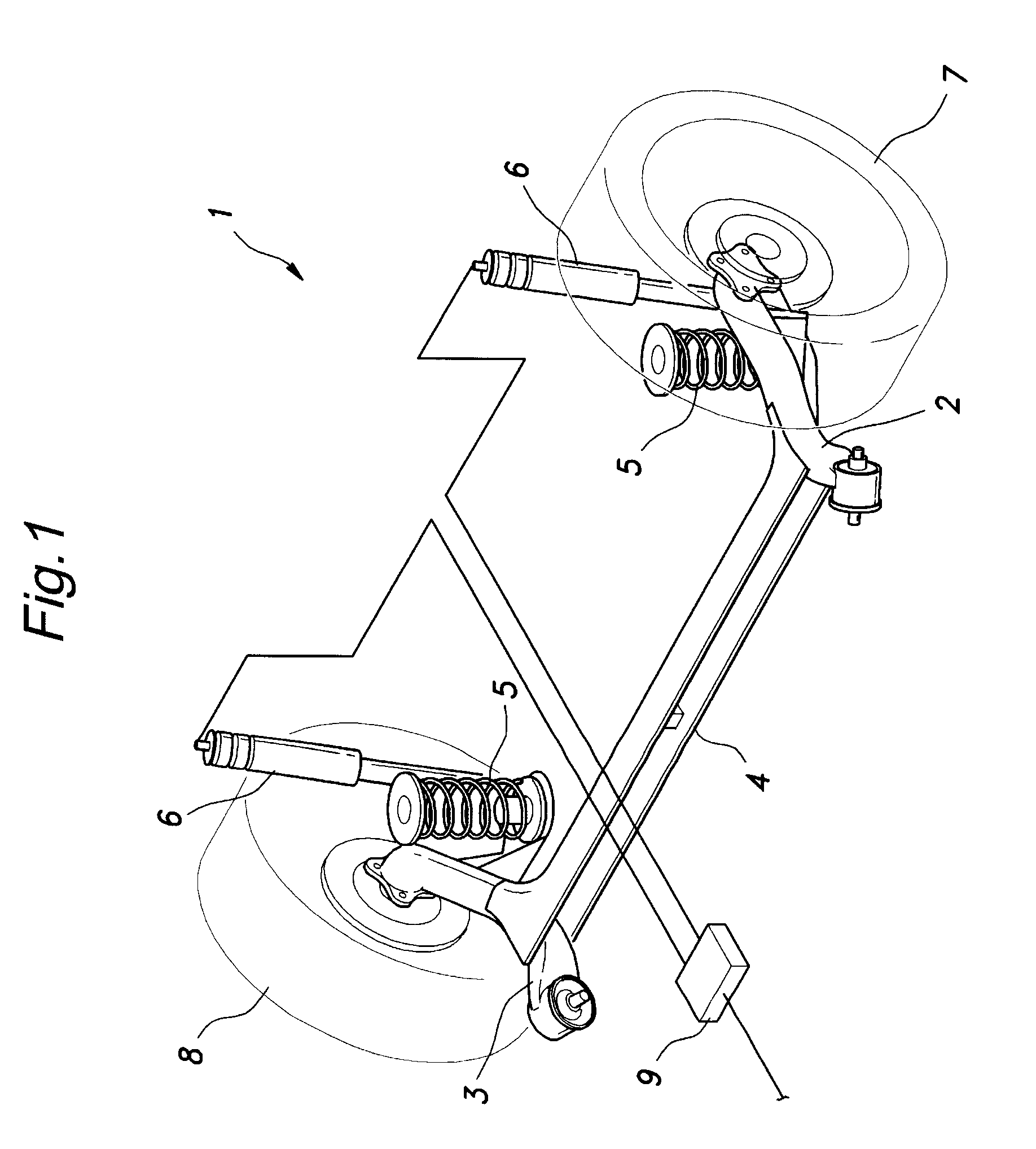
[0032]FIG. 1 shows a rear wheel suspension system 1 consisting of a H-shaped torsion beam suspension system to which the present invention is applied. This suspension system comprises a pair of trailing arms 2 and 3, a torsion beam 4 connecting intermediate parts of the trailing arms 2 and 3 with each other, a pair of coil springs 5 serving as suspension springs for the corresponding trailing arms, respectively, and a pair of dampers 6 for the corresponding trailing arms. Each damper 6 consists of a variable damping force damper using MRF (Magneto-Rheological Fluid), and is configured to vary the damping force thereof under the control of an ECU 9 mounted in a car trunk or the like.

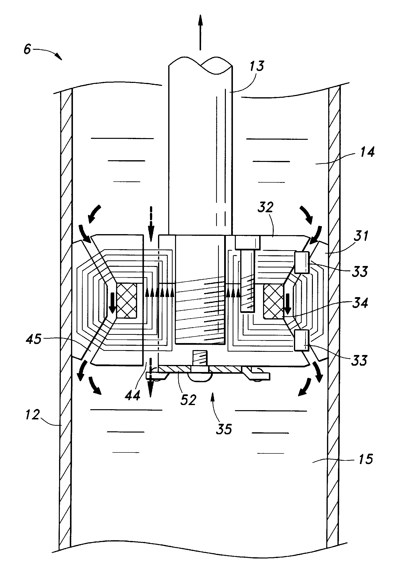
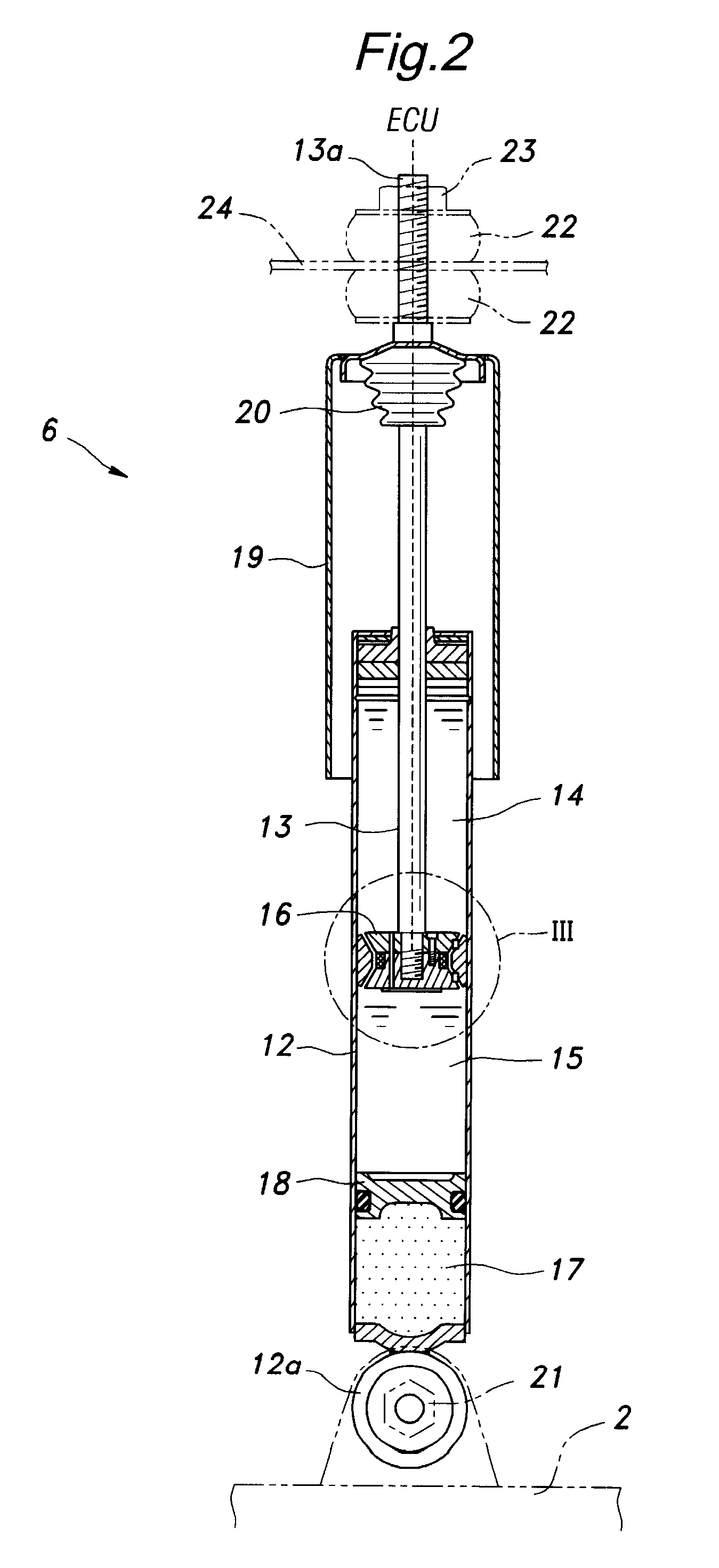
[0033]As shown in FIG. 2, the damper 6 of the illustrated embodiment consists of a mono-tube type comprising a cylindrical cylinder 12 filled with MRF, a piston rod 13 extending out of the cylinder 12 in a slidable manner, a piston 16 attached to the inner end of the piston rod 13 and separating the inter...


PUM


Abstract

In a variable damper using magneto-rheological fluid that comprises a cylinder (12) filled with the fluid, a piston (16) slidably received in the cylinder and including an inner yoke (32; 62; 126), an outer yoke (31; 64, 65; 140) and a coil (34; 130), a piston rod (13) having an inner end attached to the piston and an outer end extending out of the cylinder and a magnetic valve formed in a gap between the inner and outer yokes, at least one of the outer yoke and inner yoke consisting of at least two parts that are joined to each other in an axial direction. The two piece arrangement of the inner yoke or outer yoke allows the end plates to be omitted because the gap spacer can be installed without requiring end plates, and this contributes to a compact design and a favorable damping property. Also, the manufacturing and servicing of the damper can be simplified. When end plates (134) are used, the freedom in the positioning of the coil is increased.

Description

TECHNICAL FIELD[0001]The present invention relates to a variable shock absorber or damper that can produce a variable damping force for use in an automotive wheel suspension system, and in particular to a variable damper that is highly compact and can vary the damping force over a wide range.BACKGROUND OF THE INVENTION[0002]Various forms of variable dampers have been proposed for use in wheel suspension systems for the purposes of improving the ride quality and achieving a motion stability of the vehicle. In a common conventional variable damper, a rotary valve is incorporated in the piston for varying an effective area of an orifice that communicates the two chambers on either side of the piston with each other, and such a rotary valve is typically actuated mechanically by using a suitable actuator. More recently, it has become more common to use magneto-rheological fluid for the actuating fluid of the damper, and control the viscosity of the fluid by supplying corresponding electr...

Claims


Application Information

Patent Timeline
Patent Type & Authority Applications(United States)
IPC IPC(8): B60G17/015
CPCB60G17/06B60G21/051B60G2202/24F16F9/535
Inventor SEKIYA, SHIGENOBUAZEKATSU, YOSHITOMO
Owner HONDA MOTOR CO LTD
Why Eureka
Try Eureka