Aerodynamic time trial bike

a time trial bike and aerodynamic technology, applied in the direction of steering devices, bicycle equipment, bicycle brakes, etc., can solve the problem of reducing the aerodynamic drag at the first portion of the seatstay, and achieve the effect of reducing aerodynamic drag, reducing aerodynamic drag, and increasing the aerodynamic drag on the bicycle less

Inactive Publication Date: 2008-10-16
FELT RACING
View PDF26 Cites 11 Cited by
  • Summary
  • Abstract
  • Description
  • Claims
  • Application Information

AI Technical Summary

Benefits of technology

[0009]A bicycle frame is provided wherein a standard side pull rear rim brake may be positioned below a drive portion of a chain and above chain stays of the bicycle frame. Another method of reducing aerodynamic drag is to shape the front surface of the frame so as to be aerodynamically shaped such that the bicycle efficiently moves through the air. Since the rear rim brake may optionally be positioned behind the front surface of the bottom bracket region of the frame, air flowing around the frame may be deflected around the rear rim brake, thus increasing the aerodynamic drag on the bicycle less than is typical for a bicycle with the rear rim brake mounted to the seat stays.
[0010]Moreover, moving the rear rim brake from the first portion of the seat stays to between the drive portion of the chain and the chain stays has a cumulative effect of reducing the aerodynamic drag. The reason is that the airflow in the region adjacent the crank arms and the riders feet is already disturbed or otherwise not laminar. Positioning the rear brake in the bottom bracket region does not further increase the instability of the airflow in that area. As such, the standard side pull rear rim brake positioned between the drive portion of the chain and chain stays does not significantly increase the aerodynamic drag on the bicycle at the bottom bracket region. Moreover, moving the standard side pull rear rim brake away from the first portio

Problems solved by technology

Moreover, moving the standard side pull rear rim brake away from the first portion of the seat stays to between th

Method used


Image

  • Aerodynamic time trial bike
  • Aerodynamic time trial bike
  • Aerodynamic time trial bike

Examples


Embodiment Construction

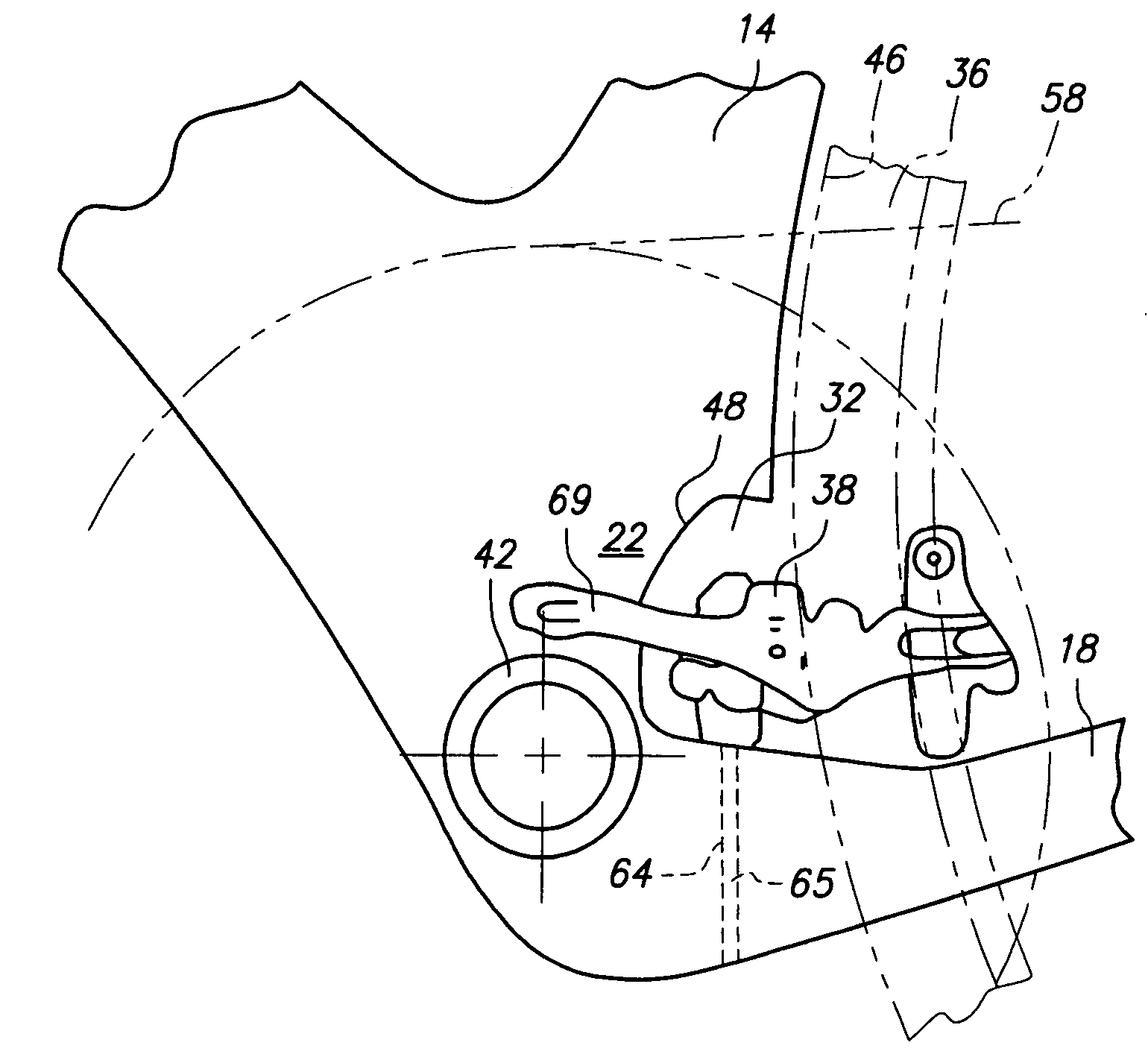
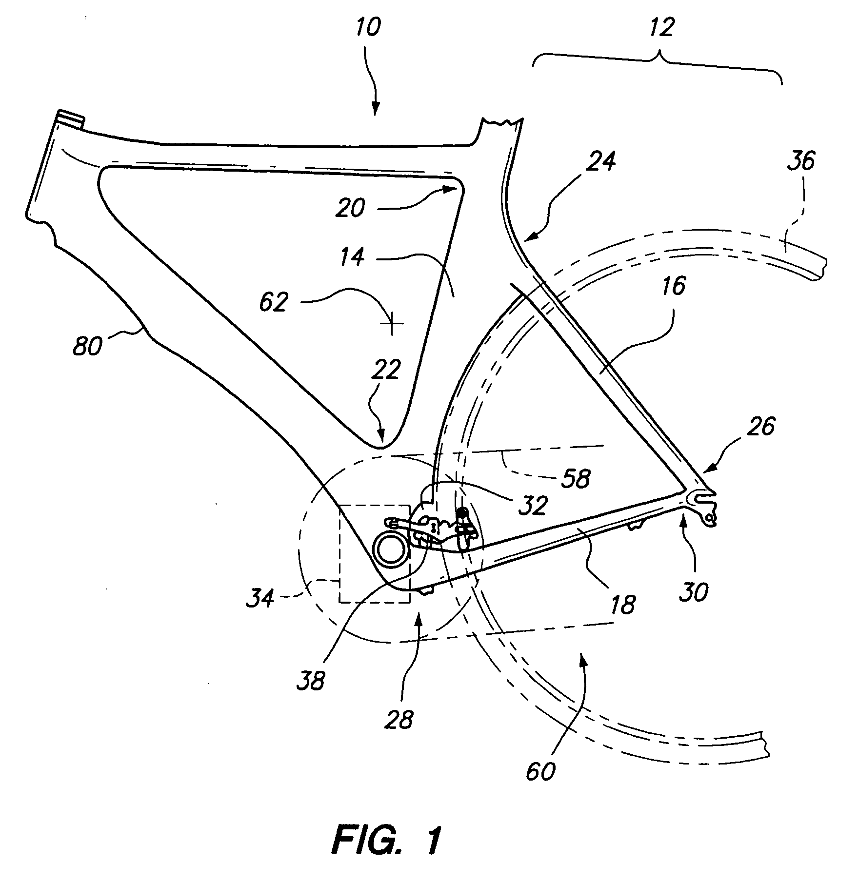
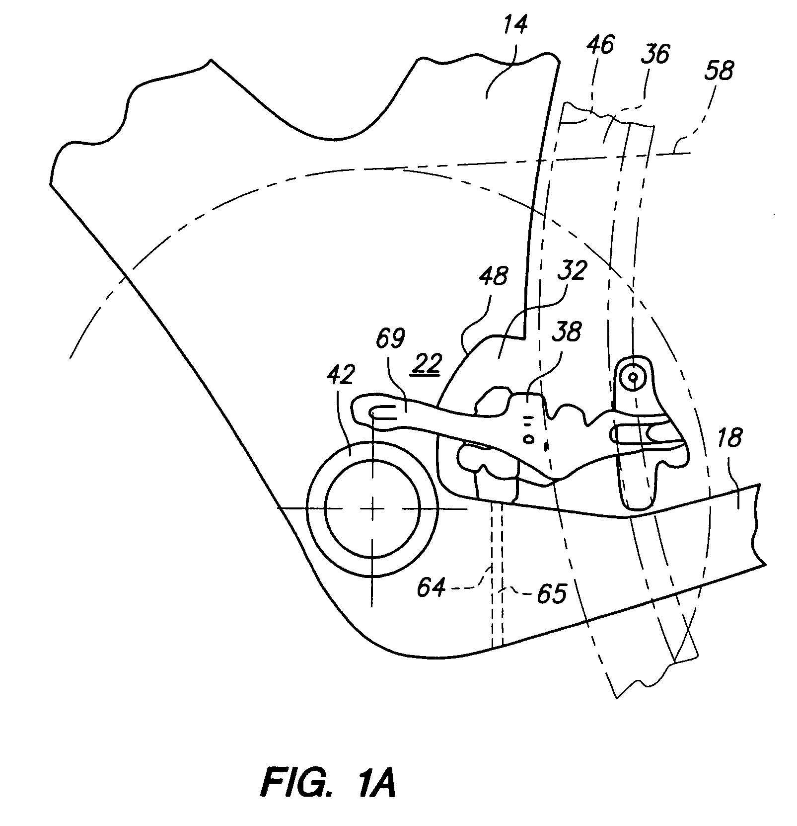
[0018]Referring now to the figures, a bicycle frame 10 is shown. The bicycle frame is formed with a rear triangle portion 12 defined by a seat tube 14, one or more seat stays 16 and one or more chain stays 18. The seat tube 14, seat stays 16 and the chain stays 18 collectively form the rear triangle portion 12. More particularly, the seat tube 14 defines an upper portion 20 and a lower portion 22. Each of the seat stay 16 defines a first portion 24 and a second portion 26. The first portions 24 of the seat stays 16 are attached to the upper portion 20 of the seat tube 14. The chain stays 18 each define a front portion 28 and a rear portion 30. The front portions 28 of the chain stays 18 are attached to the lower portion 22 of the seat tube 14. The rear portions 30 of the chains stays 18 are attached to the second portions 26 of the seat stays 16. The various aspects of the invention will be discussed in relation to a bicycle frame having a seat tube 14 and chain stays 18. However, i...


PUM


Abstract

An aerodynamic racing bicycle is provided. The racing bicycle may have a rear rim brake positioned below a drive portion of a chain and above a chain stay for reducing the aerodynamic drag on the bicycle.

Description

CROSS-REFERENCE TO RELATED APPLICATIONS[0001]Not ApplicableSTATEMENT RE: FEDERALLY SPONSORED RESEARCH / DEVELOPMENT[0002]Not ApplicableBACKGROUND[0003]The present invention relates to a standard side pull rear rim brake caliper positioned below a drive portion of a chain and above the chain stays of a bicycle with a brake actuating arm positioned on a non drive side of the bicycle and away from operation of the front derailleur and chain drive components.[0004]A modern bicycle may be designed with consideration for the aerodynamic drag on the bicycle. Reducing the aerodynamic drag allows increased speed without increased effort by the rider. One portion of the bicycle that creates drag is the rear rim brake.[0005]The rear rim brake is typically mounted to seat stays of the bicycle frame. While the bicycle moves forward, the rear rim brake moves through the air creating aerodynamic drag. The reason is that due to functional requirements, standard side pull rim brake calipers that are c...

Claims


Application Information

Patent Timeline
IPC IPC(8): B62K3/04
CPCB62K3/04B62K19/38B62K2025/041F16D55/2245
Inventor LANE, TIMOTHY SAUL
Owner FELT RACING
Why Eureka
Try Eureka