Eureka AIR delivers breakthrough ideas for toughest innovation challenges, trusted by R&D personnel around the world.

Thin-Film Magnetic Head and Manufacturing Method Thereof

Active Publication Date: 2008-10-16
TDK CORPARATION
View PDF6 Cites 13 Cited by
  • Summary
  • Abstract
  • Description
  • Claims
  • Application Information

AI Technical Summary

Benefits of technology

[0009]It is therefore an object of the present invention to provide a thin-film magnetic head and a manufacturing method of a thin-film magnetic head, whereby a width of a free layer can be narrowed without lowering a shield effect of a lower magnetic shield layer.
[0010]According to the present invention, a thin-film magnetic head includes a lower magnetic shield layer, an MR multi-layered structure formed on the lower magnetic shield layer so that current flows in a direction perpendicular to surfaces of laminated layers, and an upper magnetic shield layer formed on the MR multi-layered structure. The lower magnetic shield layer consists of a first soft magnetic layer and a second soft magnetic layer laminated on and magnetically connected with the first soft magnetic layer. A part of an upper surface of the first soft magnetic layer outside both side ends in a track-width direction of the MR multi-layered structure is located lower in height than an upper surface within a region where the MR multi-layered structure is formed, of the lower magnetic shield layer. The second soft magnetic layer is formed outside both side ends in a track-width direction of the MR multi-layered structure. Namely, this second soft magnetic layer is formed in a dug part produced by performing over-etching or excess etching in the lower magnetic shield layer and arranged outside both side ends in a track-width direction of the MR multi-layered structure. Since the over-etching is performed, it is possible to narrow the width of the free layer. Also, because the second soft magnetic layer is laminated thereon, it is possible to prevent lowering in shield effect of the lower magnetic shield layer at the end surfaces in a track-width direction of the free layer.
[0011]It is preferred that at least a part of an upper surface of the second soft magnetic layer is located upper in height than the upper surface within the region where the MR multi-layered structure is formed, of the lower magnetic shield layer. Therefore, the shield effect of the lower magnetic shield layer can be more improved to further increase resolution of the thin-film magnetic head in the track-width direction.
[0012]It is also preferred that the second soft magnetic layer is in contact with parts of side end surfaces in a track-width direction of the MR multi-layered structure. In this case, more preferably, the MR multi-layered structure has a magnetization-fixed layer, a tunnel barrier layer or spacer layer laminated on the magnetization-fixed layer, and a magnetization-free layer laminated on the tunnel barrier layer or spacer layer. Also, the second soft magnetic layer terminates at side end surfaces in the track-width direction of the magnetization-fixed layer of the MR multi-layered structure or at side end surfaces in the track-width direction of a layer of the MR multi-layered structure, nearer to the lower magnetic shield layer than the magnetization-fixed layer. Therefore, the shield effect of the lower magnetic shield layer can be more improved to further increase resolution of the thin-film magnetic head in the track-width direction.
[0015]According to the present invention, also, a manufacturing method of a thin-film magnetic head includes a step of depositing MR multi-layered films on a lower magnetic shield layer made of a soft magnetic material, a step of etching the deposited MR multi-layered films for defining a track width to form a MR multi-layered structure, the etching being performed until a part of the lower magnetic shield layer is over-etched, a step of filling the over-etched part of the lower magnetic shield layer by a soft magnetic material, and a step of forming an upper magnetic shield layer on the MR multi-layered structure. Since a soft magnetic material fills the over-etched part of the lower magnetic shield layer, it is possible to prevent lowering in shield effect of the lower magnetic shield layer at the end surfaces in a track-width direction of the free layer. Furthermore, because the over-etching is performed, it is possible to narrow the width of the free layer.

Problems solved by technology

Because the CPP structure utilizes magnetic shield layers themselves as electrodes, short-circuit or insufficient insulation between magnetic shield layers and element layer, which had been serious problem for narrowing the read gap in the CIP structure never inherently occurs.
However, because there is a physical limitation in narrowing the width of the mask made of a resist material, according to the conventional fabrication method in general, the width of the MR multi-layered structure itself was narrowed as much as possible by performing excess milling.
Such excess milling might induce over-etching of not only the MR multi-layered structure itself but also the lower magnetic shield layer in the regions outside both side ends of the MR multi-layered structure.
Also, because the point (2) contributes in no small part to increase resolution in the bit direction, the over-etching may deteriorate the bit resolution.

Method used


Image

  • Thin-Film Magnetic Head and Manufacturing Method Thereof
  • Thin-Film Magnetic Head and Manufacturing Method Thereof
  • Thin-Film Magnetic Head and Manufacturing Method Thereof

Examples


Embodiment Construction

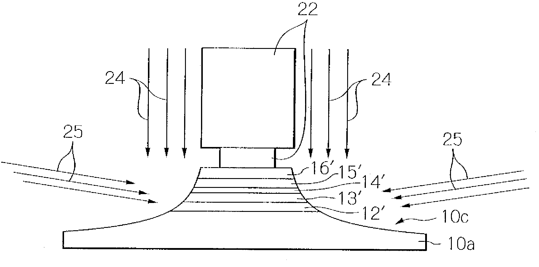
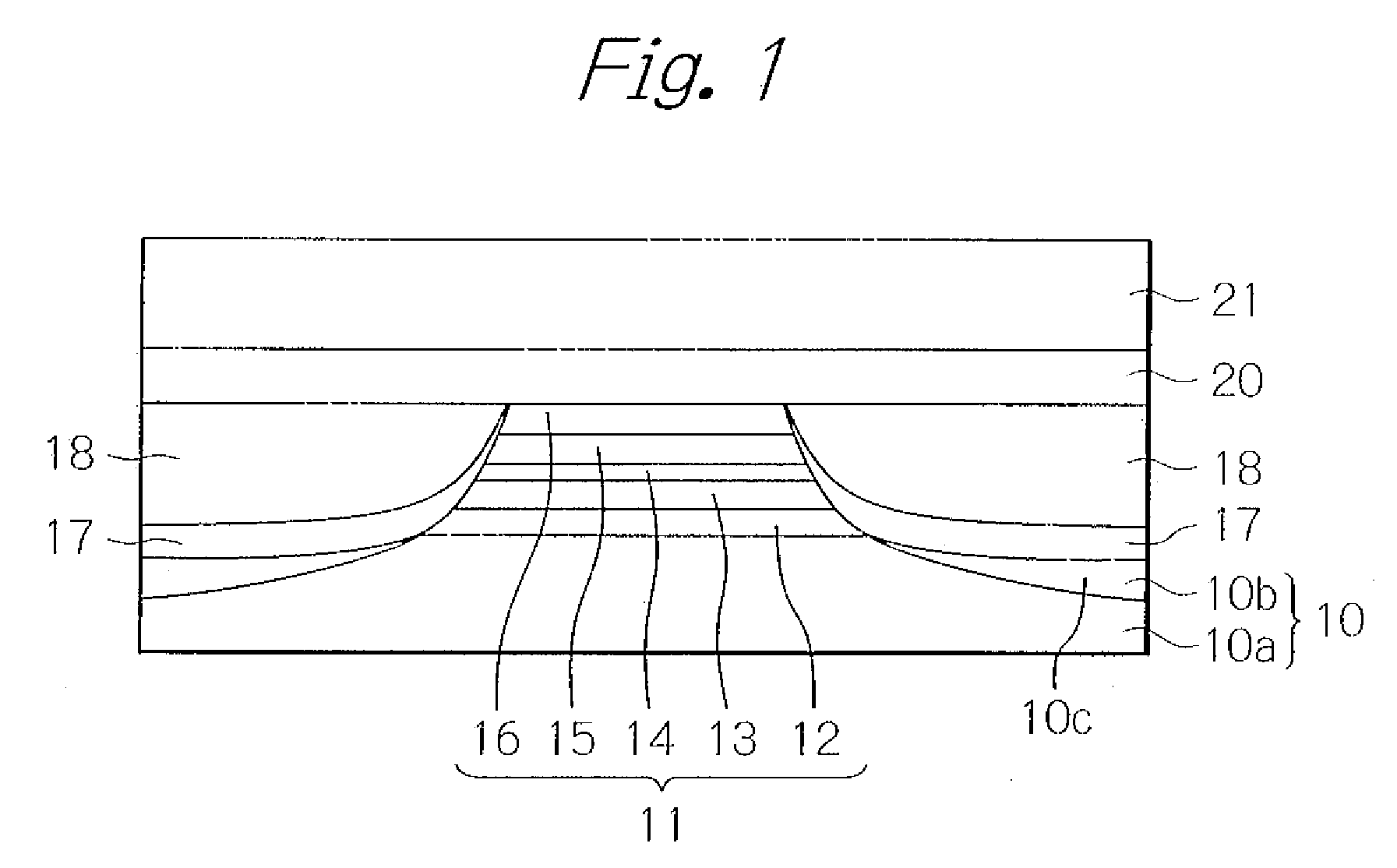
[0034]FIG. 1 schematically illustrates a TMR read head element part of a thin-film magnetic head seen from an air-bearing surface (ABS) as a preferred embodiment according to the present invention. In the figure, to ensure greater ease in understanding the present invention, indicated are only main layers.

[0035]As shown in the figure, the TMR read head element part of the thin-film magnetic head in this embodiment has a lower magnetic shield layer 10 that doubles as a lower electrode and is made of a soft magnetic material, and a TMR multi-layered structure 11 laminated thereon. The TMR multi-layered structure 11 has a lower metal layer 12 made of a nonmagnetic metal material, a magnetization-fixed layer 13 consisting of a pin layer made of an anti-ferromagnetic material and a pinned layer with multi-layers made of a ferromagnetic material and a nonmagnetic material, a tunnel barrier layer 14 made of an insulation material, a magnetization-free layer (free layer) 15 made of a ferrom...


PUM

PropertyMeasurementUnit
Angleaaaaaaaaaa
Angleaaaaaaaaaa
Nanoscale particle sizeaaaaaaaaaa

Abstract

A thin-film magnetic head includes a lower magnetic shield layer, an MR multi-layered structure formed on the lower magnetic shield layer so that current flows in a direction perpendicular to surfaces of laminated layers, and an upper magnetic shield layer formed on the MR multi-layered structure. The lower magnetic shield layer consists of a first soft magnetic layer and a second soft magnetic layer laminated on and magnetically connected with the first soft magnetic layer. A part of an upper surface of the first soft magnetic layer outside both side ends in a track-width direction of the MR multi-layered structure is located lower in height than an upper surface within a region where the MR multi-layered structure is formed, of the lower magnetic shield layer. The second soft magnetic layer is formed outside both side ends in a track-width direction of the MR multi-layered structure.

Description

BACKGROUND OF THE INVENTION[0001]1. Field of the Invention[0002]The present invention relates to a thin-film magnetic head with a magnetoresistive effect (MR) element for detecting magnetic intensity in a magnetic recording medium and for outputting a read signal, and to a manufacturing method of the thin-film magnetic head.[0003]2. Description of the Related Art[0004]Recently, in order to satisfy the demand for higher recording density and downsizing in a hard disk drive (HDD) apparatus, higher sensitivity and resolution of a thin-film magnetic head are required. Thus, as for a thin-film magnetic head with a recording density performance of 100 Gbspi or more, a tunnel magnetoresistive effect (TMR) head with a TMR read head element having a current perpendicular to plane (CPP) structure capable of achieving higher sensitivity and resolution is coming into practical use instead of a general giant magnetoresistive effect (GMR) head with a GMR read head element having a current in plan...

Claims


Application Information

Patent Timeline
IPC IPC(8): G11B5/33B05D5/12
CPCB82Y25/00G01R33/093G11B5/11Y10T29/49046G11B5/3912G11B5/398G11B5/3163
Inventor KAGAMI, TAKEOKANAYA, TAKAYASU
Owner TDK CORPARATION
Why Eureka
Eureka Blog
Learn More