Dental Implant System and Method

a technology of dental implants and taper connections, which is applied in the field of dental implants, can solve the problems of difficult to prevent the rotation of the implant abutment, insufficient tolerance in the manufacturing process, and inconvenient etc., and achieve the effect of accurate placement of the abutmen

Active Publication Date: 2008-10-16
BONDAR
View PDF17 Cites 28 Cited by
  • Summary
  • Abstract
  • Description
  • Claims
  • Application Information

AI Technical Summary

Benefits of technology

[0015]One aim of the present invention is to provide a dental implant system and method which is capable of eliminating the disadvantages of the prior art and in particular a dental implant system which has surface and structural features which provide accurate placement of the abutment and replication of the implantation site.

Problems solved by technology

Known implant systems utilizing screw-less internal Morse taper connections have inherent disadvantages when compared to more widely used screw retained, internal or external hex dental implants.
These disadvantages include: (1) the round shape of the female and male components makes it difficult to register the position of the prepared implant abutment; (2) the implant abutment may not travel in a straight line when tapped into the implant; (3) the round shape of the female and male components makes it difficult to prevent rotation of the implant abutment once the final restoration is under stress; (4) the implant abutment may be over-inserted into the implant as compared to the implant analog; and (5) the implant abutment may not be inserted into the implant as far as it was inserted into the implant analog.
Tolerances used in manufacturing process are not adequate for reproduction of abutment insertion distance over the implant analog and the implant.
But the benefit of the locking taper connection will be lost.
Some patients may find the use of tapping action to seat the abutment onto the implant uncomfortable.
It is understood that the projection tends to increase the total height of the implant, subjecting the implant to more healing disrupting stress from mastication and tongue movements.
The projection also makes fabrication of angled abutments more difficult.
Also, the abutment of the aforementioned patent cannot be easily removed or replaced without damaging the abutment, crown or opposing dentition.
In addition, it would be difficult if not impossible for the abutment and implant hex surfaces to mate accurately and for the conical or Morse tapered connection to operate properly at the same time.
This would result in a significant rotational movement between the hexes during implant indexing and during abutment insertion.
The end result is most likely a restoration which does not fit properly.
The size of the housing and O-ring abutment is critical because the available space inside the denture can be quite limited.
While further reduction of the height and width can be accomplished by reducing the thickness of the O-ring and the diameter of the spherical end of the abutment, such modifications will lead to diminished retention capability.
For this type of dental attachment assembly, the range of motion is limited to the amount of “give” the liner has.
Also, the cost of manufacturing the liner is higher when compared to O-rings.
On the contrary, if few teeth or implants are used, the semi-rigid connection, which allows slight movement only along the vertical axis of the attachment, will apply too much stress on supporting teeth or implants and can lead to their failure.
If the work is done on upper back teeth, it is easily seen that the screw removal tool can slip out of fingers and end up being swallowed or inhaled by the patient.
Having the tool of this size also requires a large space between the carrier and the opposing teeth.
Thus, at least three instruments are used with unnecessary risk of the implant coming loose and falling out of socket before the implant is securely anchored to the bone.

Method used


Image

  • Dental Implant System and Method
  • Dental Implant System and Method
  • Dental Implant System and Method

Examples


Embodiment Construction

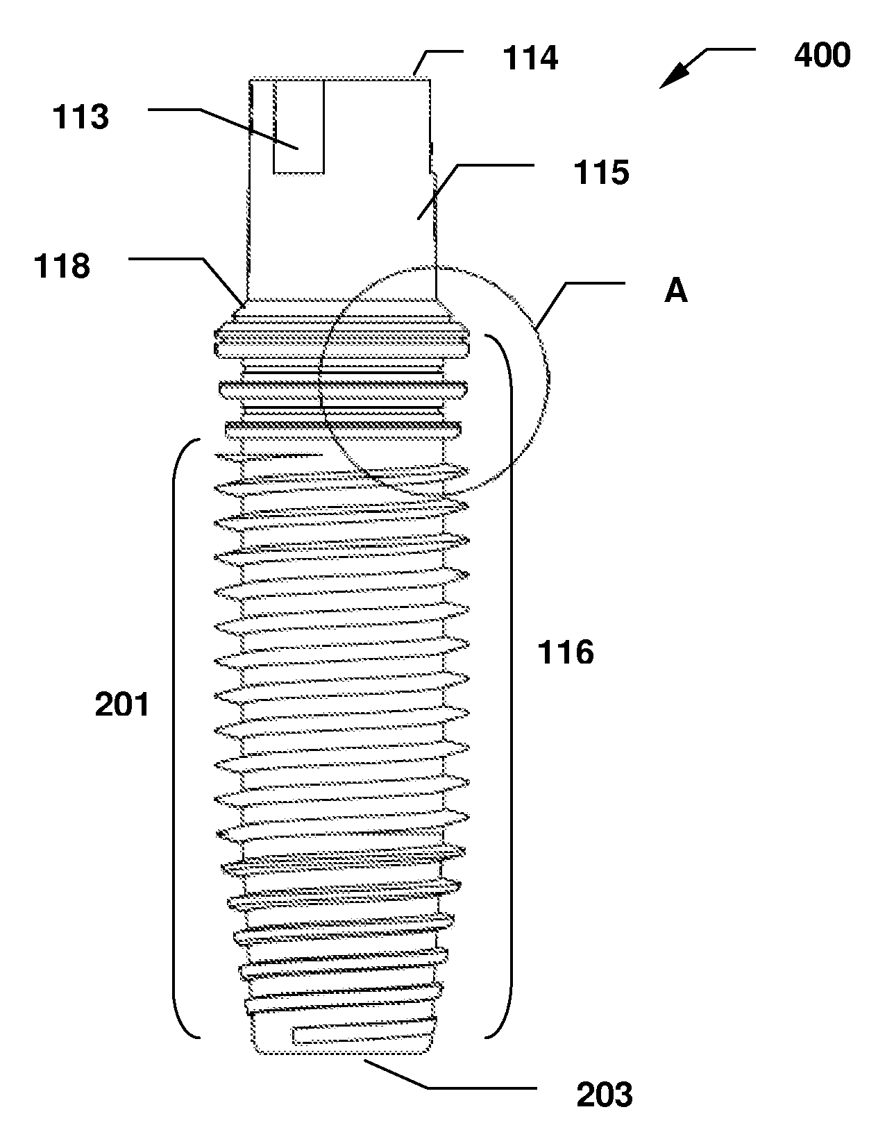
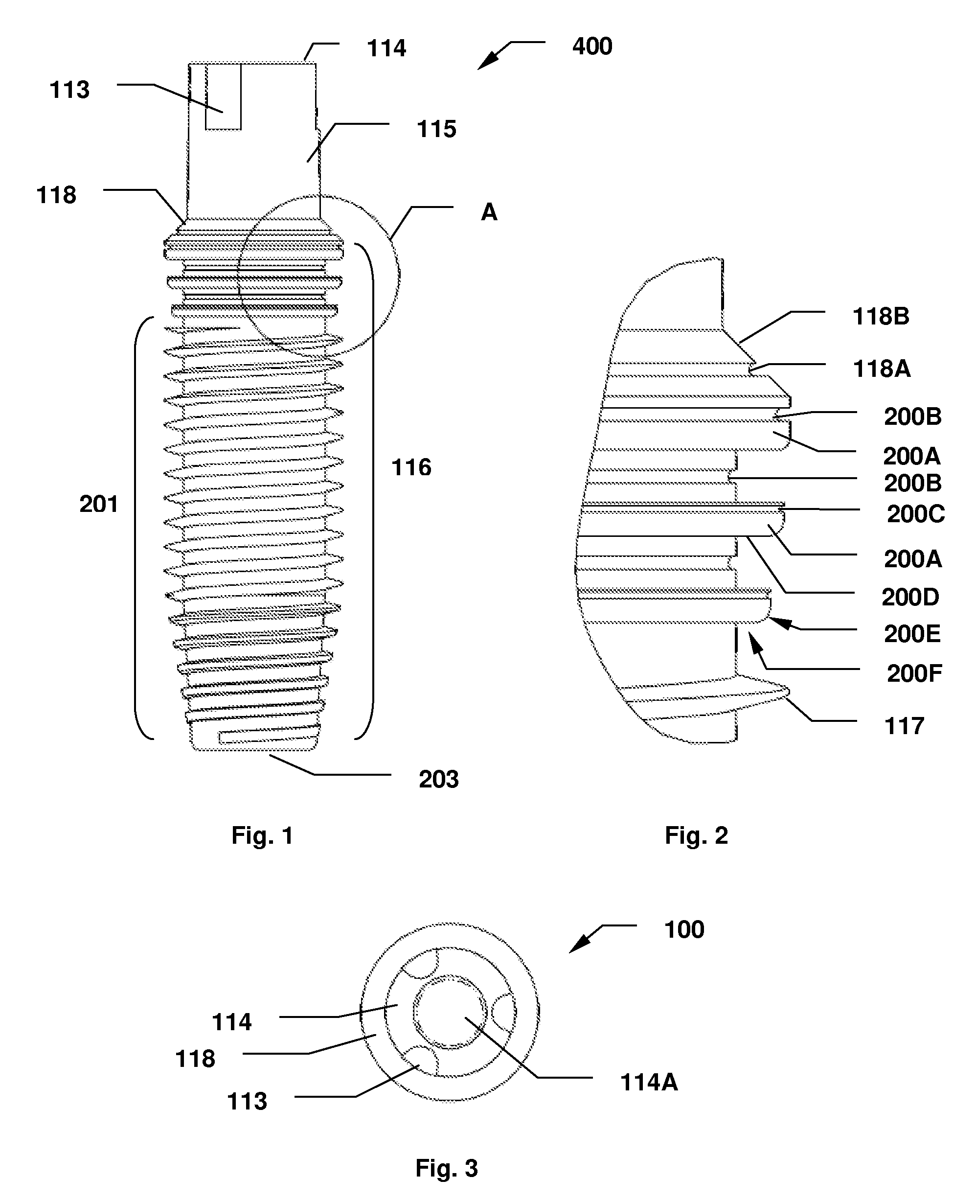
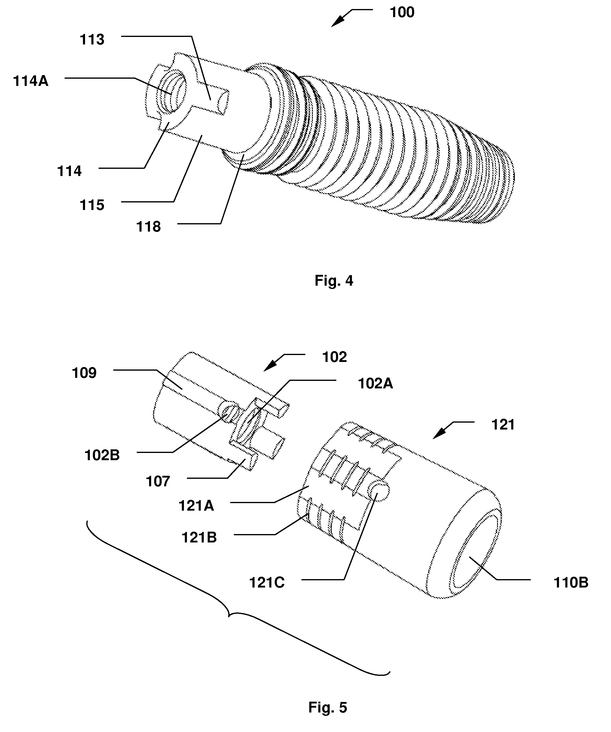
[0055]Referring now to the drawings, in which like reference numerals are used to refer to the same or similar elements, FIGS. 3-10 illustrate the dental implant system or assembly of the present invention, which comprises a dental implant 100, a key 102, an implant abutment 121, an abutment insertion tool 205, an abutment removal tool 206 and an implant insertion and removal tool 207.

[0056]As shown in FIG. 4, the dental implant 100 is formed as an elongated body having an anchoring portion 116, an abutment receiving portion 115 and an internally threaded opening 114A of a predetermined depth, which is accessible from the top end 114 of the dental implant 100. The abutment receiving portion 115 can also be adapted to receive a prosthesis, such as a crown or a bridge, without the use of an abutment or the abutment being attached to it first. Preferably, the dental implant 100 has a cylindrical shaped body, and / or an annular shoulder 118 disposed between the anchoring portion 116 and ...


PUM


Abstract

A dental implant system comprising an implant member, an abutment member and a transfer key with cooperatively engaging structures for ensuring proper alignment and orientation of an abutment assembled on the implant member and for preparing an accurate dental impression and mold which represents the implantation site and its relationship to adjacent teeth structures. The abutment has the advantage of being easily removed for maintenance, repair or replacement with minimal or no discomfort to the patient. The invention also includes a dental implant with an improved bone-engaging structure for enhancing implant stability and fixation, an O-ring type abutment assembly with a reduced footprint in its assembled state when compared with similar conventional systems, a surgical screw and bone screw insertion tool, a healing abutment that need not be removed during an impression taking procedure, and an implant coding system that facilitates selection and identification of dental implants and implant analogs whose dimensional attributes will produce an accurate fit between the dental prosthesis and the dental implant. Further, dental reconstruction and abutment installation methods utilizing the dental implant system and instruments of the invention are disclosed.

Description

CROSS REFERENCE TO RELATED PATENT APPLICATIONS[0001]This application is a Continuation-In-Part of U.S. Ser. No. 11 / 615,131, filed Dec. 22, 2006 and U.S. Ser. No. 11 / 737,687, filed Apr. 19, 2007, and claims benefit of U.S. Ser. No. U.S. Ser. No. 60 / 834,891, filed Aug. 1, 2006. The preceding applications are incorporated herein by reference in their entireties.FIELD AND BACKGROUND OF THE INVENTION[0002]The present invention relates in general to a dental implant system comprising components having improved surface and structural features for ensuring proper alignment and orientation of an abutment assembled on an implant and for preparing an accurate dental impression and mold representing the implantation site and its relationship to adjacent teeth structures. The present invention also relates to an implant having improved bone engaging surfaces for enhancing implant stability and fixation. The present invention further relates to a multi-component dental implant system with at leas...

Claims


Application Information

Patent Timeline
Patent Type & Authority Applications(United States)
IPC IPC(8): A61C8/00
CPCA61C8/0001A61C8/0018A61C8/0022A61C8/0048A61C8/005A61C8/0054A61C8/006A61C8/0066A61C8/0069A61C8/0071A61C8/0087A61C8/0089A61C2008/0046
Inventor BONDAR, VITALI
Owner BONDAR
Why Eureka
Try Eureka