
Control System and Teach Pendant For An Industrial Robot

a technology of industrial robots and control systems, applied in the field of teaching pendants, can solve the problems of large tpus, operator fatigue, etc., and achieve the effects of reducing the effort required to program the robot, improving ease of use, and simple and comfortable methods of jogging the robo

Inactive Publication Date: 2008-10-16
ABB AS
View PDF19 Cites 48 Cited by
  • Summary
  • Abstract
  • Description
  • Claims
  • Application Information

AI Technical Summary

Benefits of technology

[0022]The improved robot controller according to an embodiment of the invention proposes a new way for moving a robot to a desired point by means of using with two simple 2-axis joysticks. The robot controller provides for mapping up to 4 axes of the robot at any one time and moving the robot using the thumb operated joysticks. The improved portable robot controller or TPU comprising two joysticks offers the advantage of considerably improved ease-of-use when compared to the prior art devices. In part, the effort required to program the robot is reduced because the movement control task may be shared between two hands as required. An important technical advantage of the improved design is that the improved TPU permits the operator to move the robot in a direction in space represented by at least 3 degrees of freedom by moving the two joysticks simultaneously in a coordinated movement. When in angle mode, the operator can change the angle of attack of the robot by moving both joysticks. The improved TP also provides the user with a simpler and easier comfortable method to jog the robot. The advantage of all these features provided by the dual joystick control arrangement is that use of the robot controller is less fatiguing for the operator.
[0023]A very significant advantage of the improved robot controller according to an embodiment of the invention is provided by comprising a safety means arranged to permit an operator to operate the robot controller using one hand only. This is also a feature that provides opportunities to reduce operator fatigue. This feature also permits a changeover of operation from one hand to the other hand such that control of the robot does not have to be interrupted. This is because the safety arrangement provides two live handle switch operating means, one being located within reach of the left hand and the other one within reach of the right hand. Thus the operator can hold one first live handle switch operating means, grip the second live handle switch operating means with the other hand, and then let go of the first live handle switch operating means, and control the robot with the second means. By doing so the operator can change hands or take away either hand from the TPU without interrupting control. The above new features of improved TPU offer considerably improved ease-of-use for an operator and also contributes to significant reductions in operator fatigue.
[0024]Another advantage of the improved TPU according to an embodiment is that the joystick may be configured or re-configured in the TPU or robot control software to assign movement axes to each joystick to suit the preferences of operators, and to easily change preferences for example for operators who are left handed or right handed. Another advantage is that the TPU may control up to 4 axes at a time, but the selection and distribution of axes such as x, y, z, and a fourth axis may be varied by configuring the TPU in the TPU or other robot control software. Commonly the left joystick may be selected to move the robot in the x and y directions, and the right joystick selected to move the robot in the z direction. When a fourth axis is present, when the robot is for example rail or track or mounted, trolley mounted, or moveable in some other way, a rail axis may be selected as a fourth axis R on, for example, the right joystick.

Problems solved by technology

However by todays standards the TPU is relatively large and heavy.
The operator may tend to experience fatigue in the hand holding the safety switch, and / or the other hand operating the joystick during a long programming cycle.

Method used


Image

  • Control System and Teach Pendant For An Industrial Robot
  • Control System and Teach Pendant For An Industrial Robot
  • Control System and Teach Pendant For An Industrial Robot

Examples


Embodiment Construction

[0032]In an embodiment of the present invention an improved TPU is described for moving a robot by means of manually influencing at least two control means, such as joysticks, and in particular, bi-directional control means or joysticks.

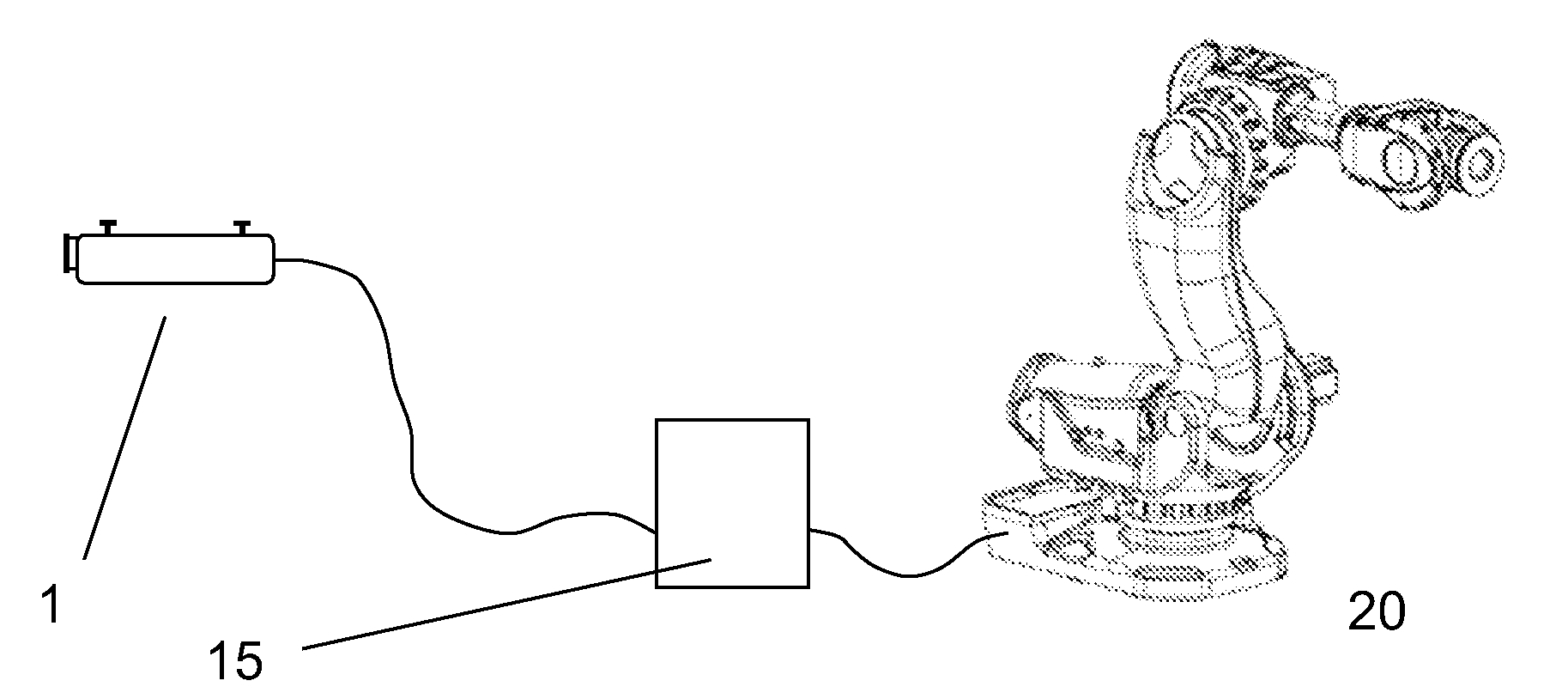
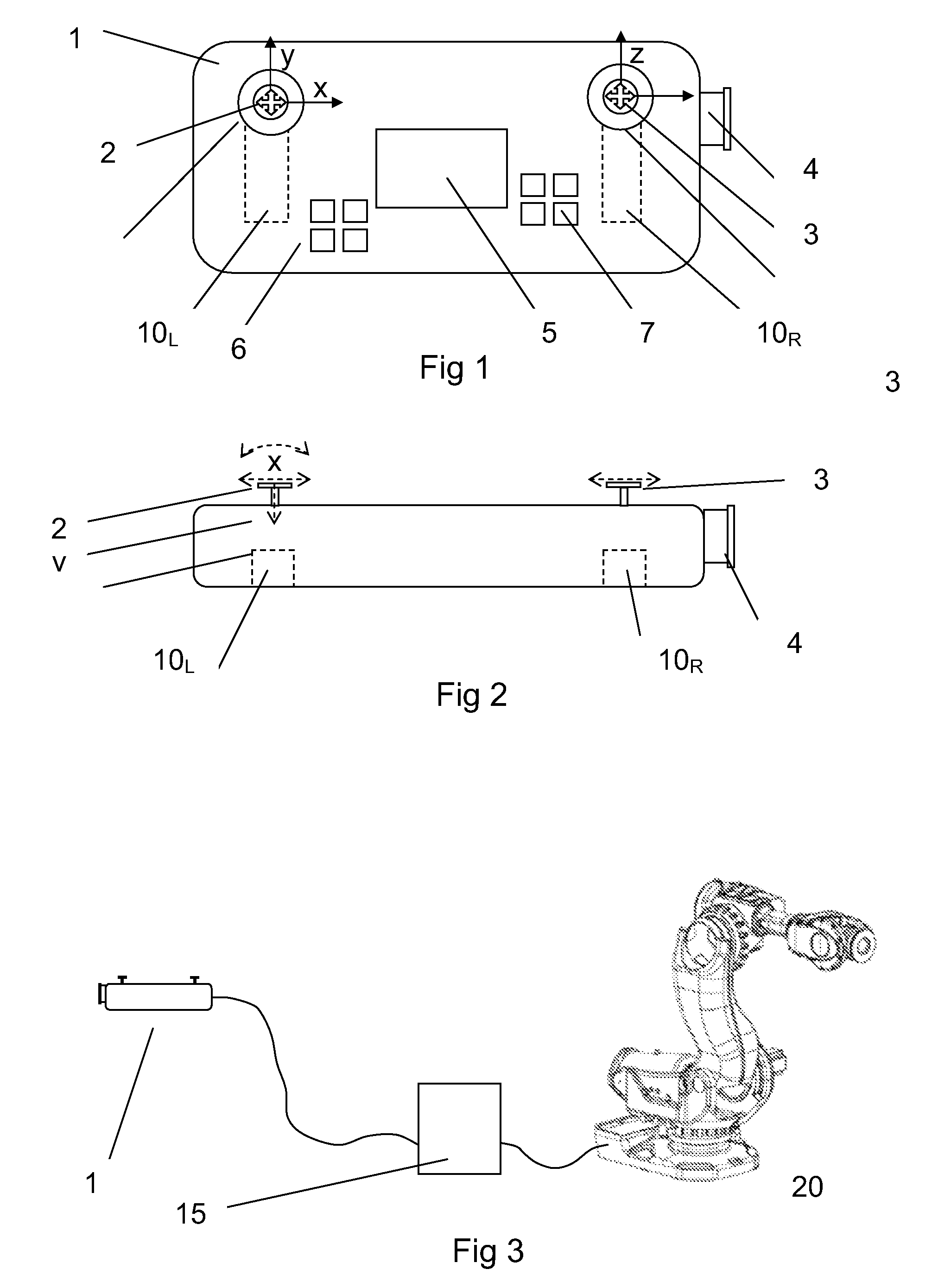
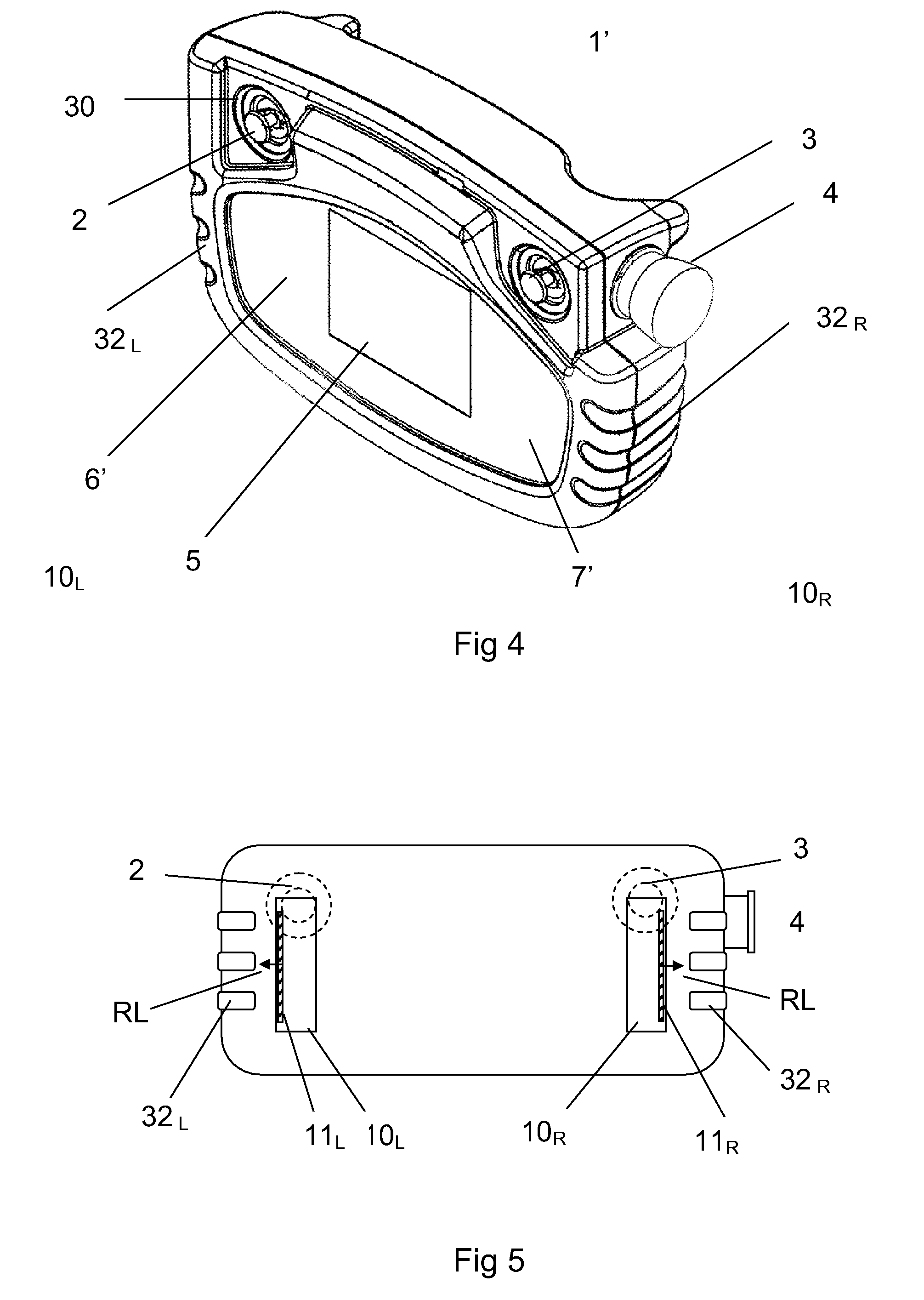
[0033]FIG. 1 shows a schematic view from above of the improved TPU of an embodiment of the invention much as an operator looking down may see it. The figure shows a TPU in the form of a panel 1 or console, including a first control means 2 and a second control means 3. An emergency stop 4 is arranged as a push button on the panel. The panel may be further arranged with a display 5 of some sort and one or more switch means 6, 7. The switch means 6 or 7 may be arranged as single pushbuttons or groups of pushbuttons. The functions of the pushbuttons are controlled by the robot control system and may be presented in plain text on the display. The pushbuttons may activate fixed functions or variable eg programmable functions. Generally each pushbutton whe...


PUM


Abstract

A robot controller for an industrial robot is described. The robot controller is a portable controller of the TPU Teach Pendant Unit type and comprises control means for moving a robot in three or more degrees of freedom. The TPU comprises a visual display and selection means associated with programming or controlling a robot. In other aspects of the invention a system comprising a robot and a control unit and the TPU are described. A computer program of the TPU for carrying out the method is also provided.

Description

CROSS-REFERENCE TO RELATED APPLICATIONS[0001]The present application is a continuation of pending International patent application PCT / IB2005 / 002965 filed on Oct. 5, 2005 which designates the United States and the content of which is incorporated herein by reference.FIELD OF THE INVENTION[0002]The invention relates to a control system for an industrial robot of the kind comprising a portable robot controller or teach pendant including a control means for manually controlling movement of a robot or manipulator arm. In particular the invention relates to an improved teach pendant unit (TPU).BACKGROUND OF THE INVENTION[0003]Manually controlled movement of a robot arm—is used especially during a programming stage in order to teach the robot to follow an operating path defined by a number of set points. A memory means in the control system may store the coordinates of said set points as position instructions and other operating instructions which, together with said set points, may defin...

Claims


Application Information

Patent Timeline
IPC IPC(8): B25J13/02B25J5/02B25J19/06B25J15/00
CPCB25J13/02B25J13/065B25J19/06H01H3/022H01H3/0253H01H9/0214H01H2009/0083H01H2217/048
Inventor BRAUT, KNUT
Owner ABB AS
Learn More