Apparatus for the Purification of Gas While Bleeding a Crank Housing

Active Publication Date: 2008-10-23
ALFDEX
View PDF8 Cites 35 Cited by
  • Summary
  • Abstract
  • Description
  • Claims
  • Application Information

AI Technical Summary

Problems solved by technology

However, it has been shown that as the operating duration increases, the washer seal is subject to some wear, and thus its sealing effect decreases.
However, in certain operating situations a large pressure increase can occur in the separator chamber, in which case, because of the intermediately connected oil collection chamber and the contacting seal washer, the pressure cannot be relieved to the driving chamber.
This affects the operation of the apparatus.
However, the turbine wheel is provided d

Method used


Image

  • Apparatus for the Purification of Gas While Bleeding a Crank Housing
  • Apparatus for the Purification of Gas While Bleeding a Crank Housing
  • Apparatus for the Purification of Gas While Bleeding a Crank Housing

Examples


Example

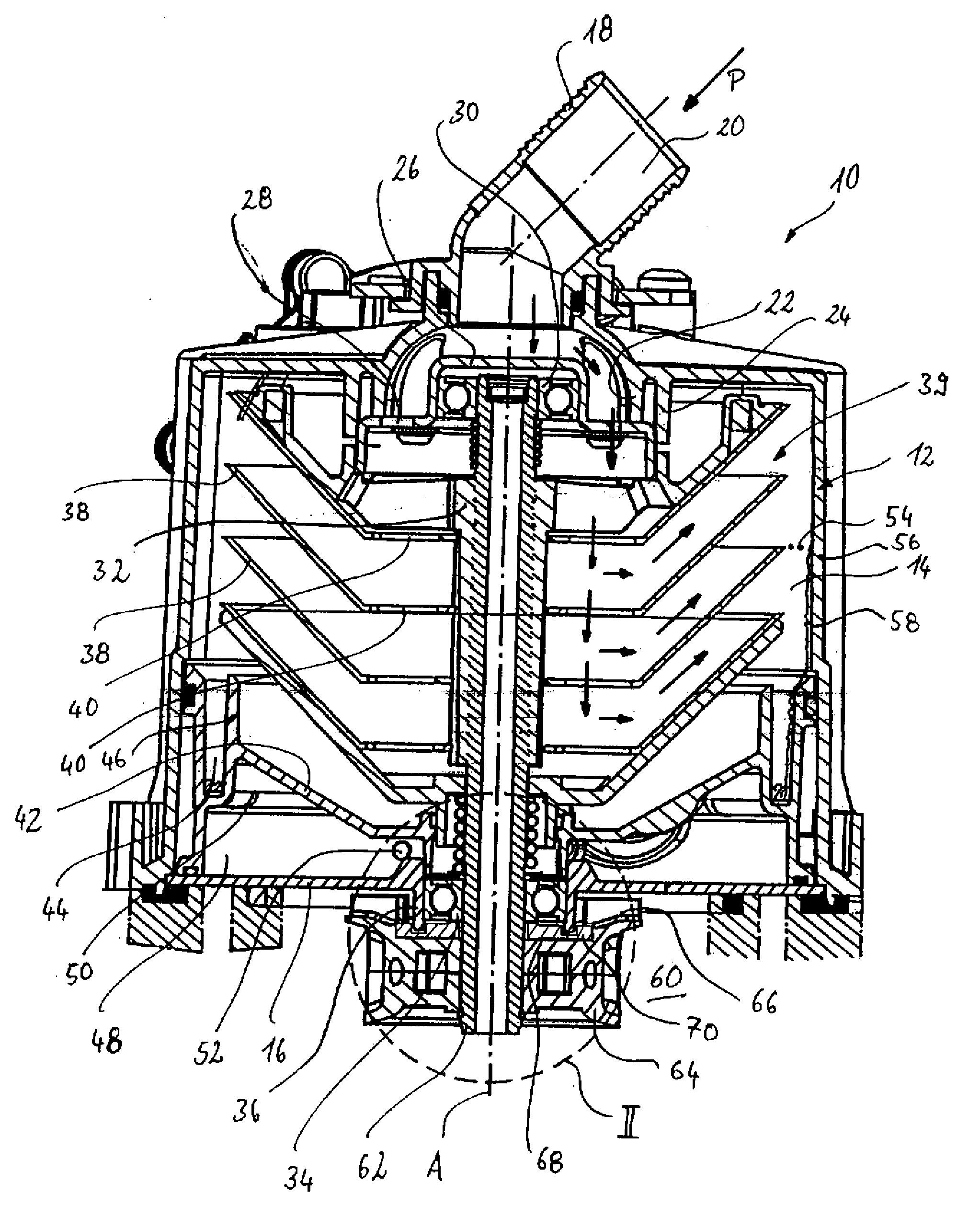
[0019]In FIG. 1, a centrifugal separating apparatus according to the invention is shown in a cross-section which includes the longitudinal axis A, and designated as a whole with 10. The separating apparatus 10 includes a housing 12, which encloses a separator chamber 14. The housing 12 is in open form downward, and sealed by a floor-side housing partition 16. In the upper zone, the housing is provided with an inlet nozzle 18, which defines an inlet 20 which opens into the separator chamber 14. In its lower zone, the housing 12 also has an outlet (not shown). Near the inlet 20, the housing 12 has holding fins 22 and 24, which receive a bearing cup 26 and hold it in the housing 12. The bearing cup 26 is in stepped form, and includes breakthroughs 28, so that the inlet 20 is connected to the separator chamber 14 for fluid.

[0020]In the bearing cup 26, a ball bearing 30 with its outer ring is received in a torque-proof manner. The inner ring of the ball bearing 30 is pressed onto a rotor...


PUM

PropertyMeasurementUnit
Thicknessaaaaaaaaaa

Abstract

The invention relates to an apparatus (10) for purifying gas while bleeding a crank housing, said apparatus (10) comprising a housing (12) inside which a separator chamber (14) is provided, a rotor arrangement with a rotor shaft (32) that is rotatably mounted in the housing and a centrifugal rotor (39) located in the separator chamber (14), and a fluid driving device (64) for driving the rotor shaft (32) by means of a driving fluid, the driving device (64) being disposed in a driving chamber (60) that is separated from the separator chamber (14) by means of a housing partition (16), and the rotor shaft (32) extending through a breakthrough in the housing partition (16). In the case of this device, it is provided that a labyrinth-type seal (70) is provided in the zone of the breakthrough in order to seal the driving chamber (60) from the separator chamber (14).

Description

SUBJECT AREA OF THE INVENTION[0001]This invention relates to an apparatus for purifying gas while bleeding a crank housing, said apparatus comprising a housing inside which a separator chamber is provided, a rotor arrangement with a rotor shaft that is rotatably mounted in the housing and a centrifugal rotor located in the separator chamber, and a fluid driving device for driving the rotor shaft by means of a driving fluid, the driving device being disposed in a driving chamber that is separated from the separator chamber by means of a housing partition, the rotor shaft extending through a breakthrough in the housing partition, and a labyrinth-type seal being provided in the zone of the breakthrough in the housing partition in order to seal the driving chamber from the separator chamber.PRIOR ART[0002]Such an apparatus is known from the prior art. The document WO 2004 / 091799 A1 shows a corresponding apparatus, using which oil particles of an oil-air mixture coming from an internal c...

Claims


Application Information

Patent Timeline
IPC IPC(8): B01D50/00F16J15/447
CPCB04B5/005B04B5/12B04B9/06B04B2005/125F01M2013/0422Y10S55/19
Inventor KUP, SERGEPOGEN, MATS-ORJANHALLGREN, INGVAR
Owner ALFDEX
Why Eureka
Try Eureka