

Motor and control circuit thereof
- Summary
- Abstract
- Description
- Claims
- Application Information
AI Technical Summary
Benefits of technology
Problems solved by technology
Method used
Image

Examples
Embodiment Construction
[0021]The present invention will be apparent from the following detailed description, which proceeds with reference to the accompanying drawings, wherein the same references relate to the same elements.
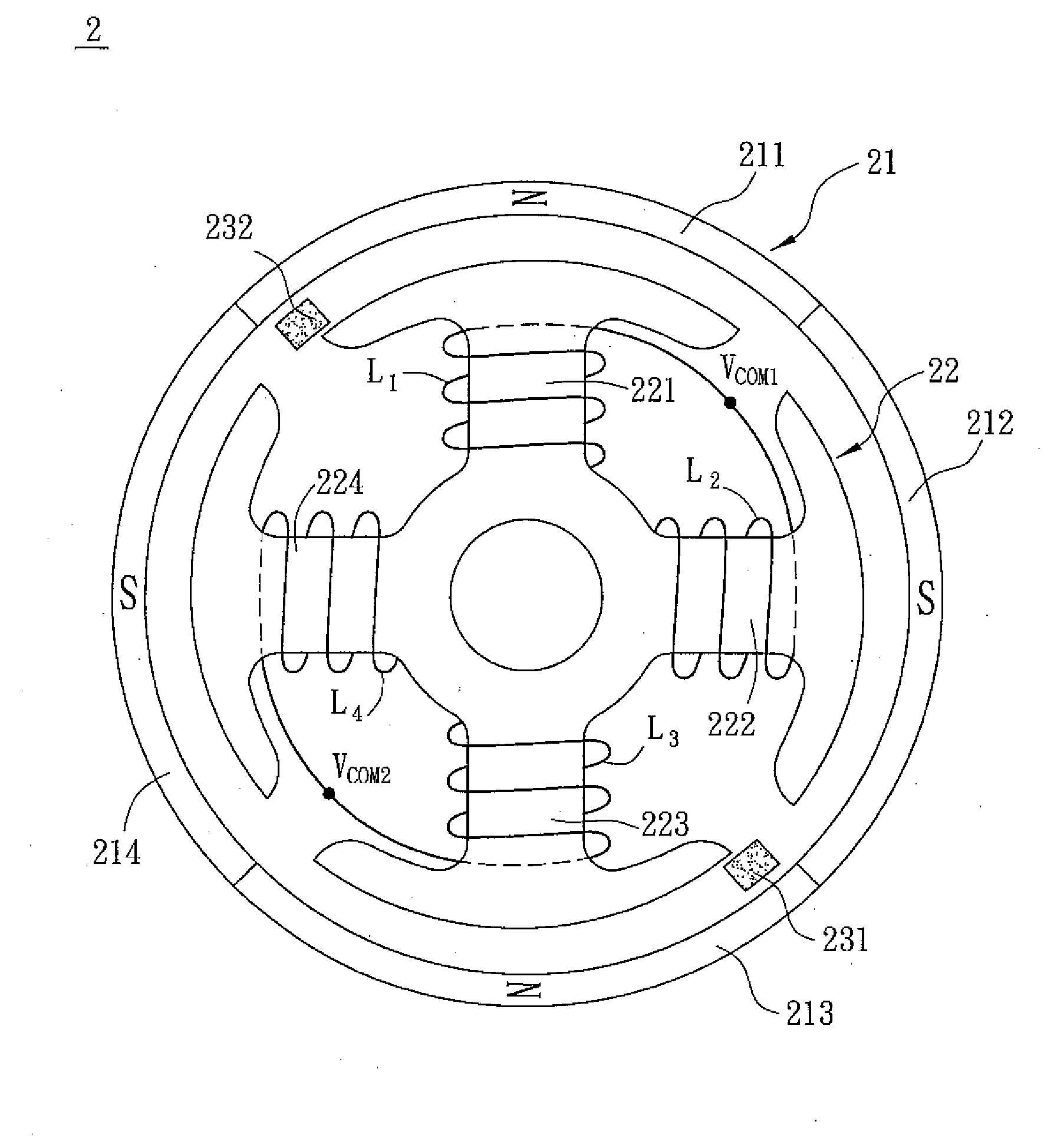
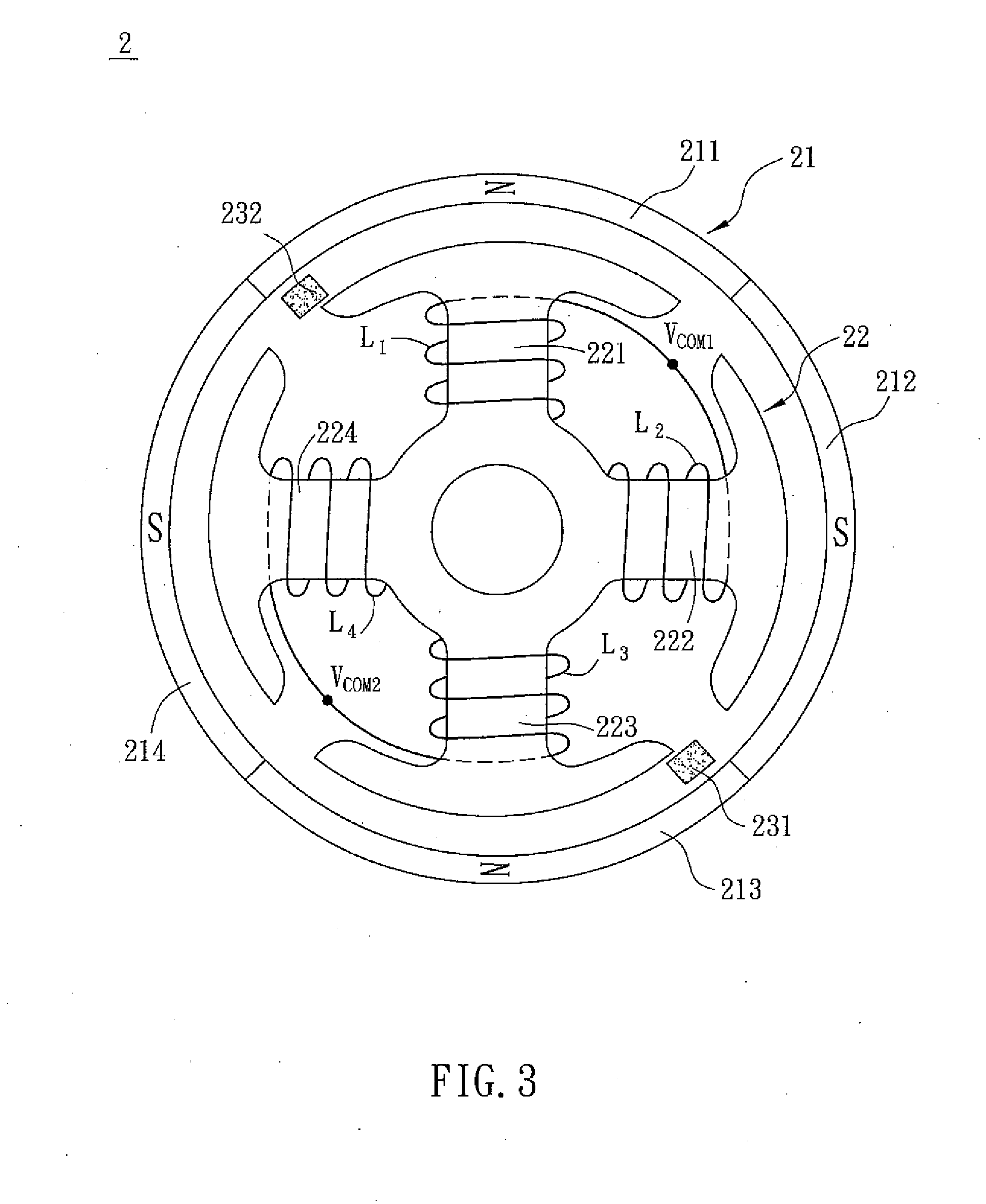
[0022]FIG. 3 is a schematic illustration showing a motor 2 according to an embodiment of the present invention. FIG. 4 is a three-dimensional diagram showing the motor 2 of FIG. 3. Referring to FIGS. 3 and 4, the motor 2 includes a rotor 21, a stator 22 and a control circuit 23.
[0023]The rotor 21 has a plurality of magnetic poles including N poles and S poles arranged alternately. In this embodiment, the rotor 21 has four magnetic poles 211, 212, 213 and 214, wherein the poles 211 and 213 are the N poles and the poles 212 and 214 are the S poles.
[0024]The stator 22 is composed of a plurality of silicon steel sheets stacked together. Herein, each silicon steel sheet has at least two sensing arms, and the sensing arms of the silicon steel sheets are respectively disposed opposite and co...
PUM
 Abstract
Description
Claims
Application Information