Dimming Circuit for Led Lighting Device With Means for Holding Triac in Conduction

a technology of led lighting and dimming circuit, which is applied in the direction of lighting and heating apparatus, process and machine control, instruments, etc., can solve the problems of low wattage, low current, and difficulty in remaining diacs, and achieve the effect of preventing ringing in the circuit and sufficient holding curren

Inactive Publication Date: 2008-10-23
DYNAMIC LED TECH LLC
View PDF9 Cites 249 Cited by
  • Summary
  • Abstract
  • Description
  • Claims
  • Application Information

AI Technical Summary

Benefits of technology

[0018]The invention described herein is a dynamic load or snubbing circuit for use with a phase control dimmer and LED lighting. The dynamic load provides sufficient current draw for the dimmer circuit and provides a current draw that will be varied depending on the current draw needs of the dimmer.

Problems solved by technology

Because of the need to hold a current, TRIACs have difficulty remaining on when a low current is drawn through the main terminals, such as in the case of LED lighting.
There a number of reasons that dimmers cause problems for LED lighting, especially low wattage LED lighting.
At smaller current levels, once the dimmer conducts, the load current does not satisfy the hold current requirement of the device, namely the TRIAC in the dimmer, and the dimmer enters a retriggering state that causes flickering of the LED light.
However, this is not a desired option.
Since LED lighting is meant to be energy efficient, putting a dummy load across the LED lighting device will cause some issues such as reduced energy efficiency, due to the power draw of the dummy load, and degeneration of heat inside LED lighting which is undesirable to the thermal management of the power electronics inside.
However, the electronic converter inside the LED converter usually has very low current consumption.
This prevents the dimmer circuit from firing properly, again causing ringing.
4. The LED converter takes time to start, therefore its current consumption requires a finite time to reach a level exceeding the hold current of the dimmer.
This delay in providing sufficient current needs to be taken into account in any circuitry.

Method used


Image

  • Dimming Circuit for Led Lighting Device With Means for Holding Triac in Conduction
  • Dimming Circuit for Led Lighting Device With Means for Holding Triac in Conduction
  • Dimming Circuit for Led Lighting Device With Means for Holding Triac in Conduction

Examples


Embodiment Construction

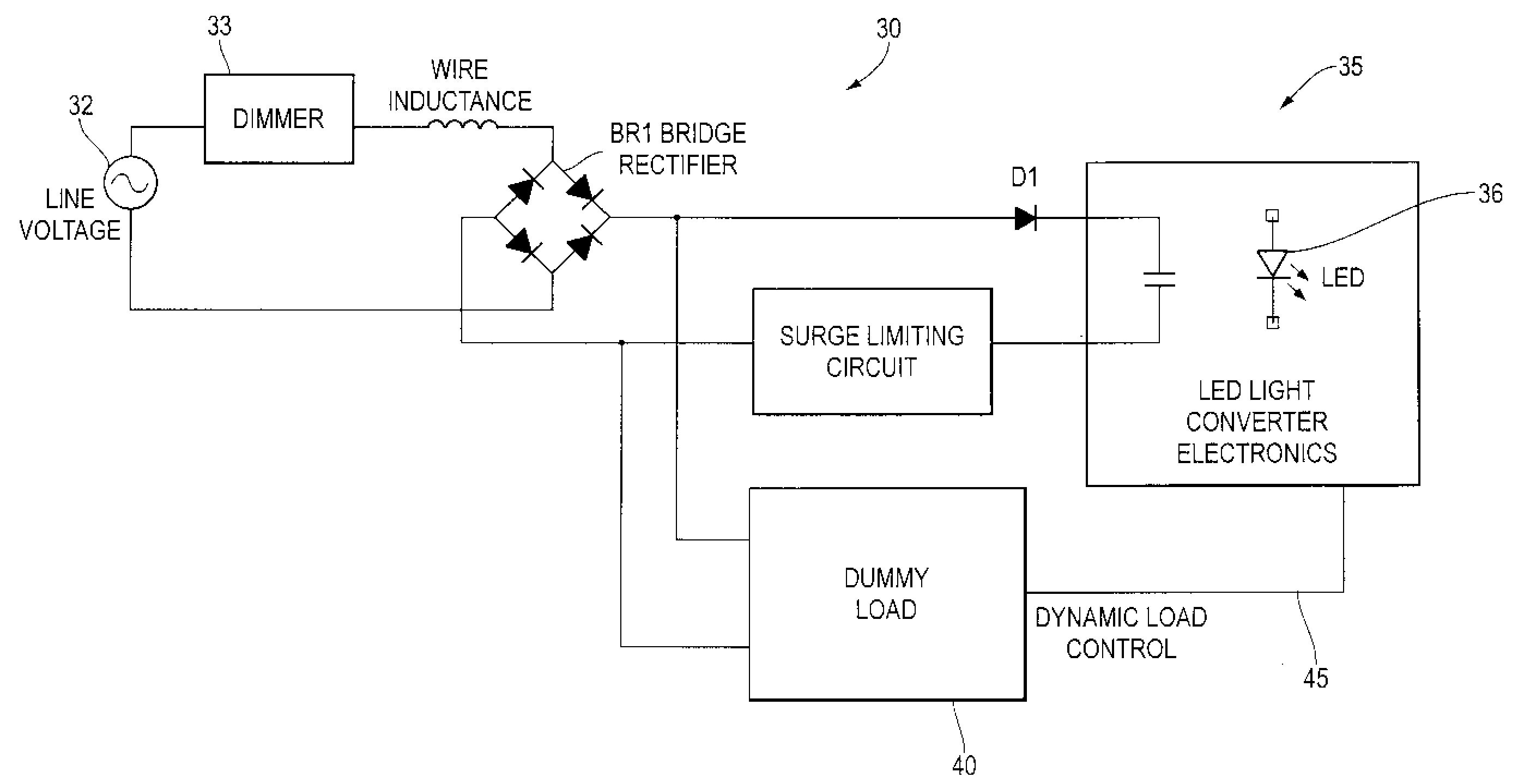
[0027]As shown in FIG. 5, the dynamic dummy load circuit 30 of the present invention is connected to an AC power source 32 electrically connected to a dimmer 33 which is electrically connected to a bridge rectifier BR1. The LED lighting converter 35 having a LED 36 is connected in parallel across the bridge rectifier BR1. The dynamic dummy load 40 is placed in parallel with the LED light converter 35. A feedback channel 45 is provided between the LED light converter 35 and the dummy load 40, so that the dummy load may be adjusted to provide an appropriate load when needed and a reduced load when not needed, thereby conserving power. The lighting converter 35 includes electronics to regulate the power received from the bridge rectifier BR1 and includes electronics to provide a control or feedback signal to the dynamic dummy load 40. The load presented to the power source or bridge rectifier BR1 by the dynamic dummy load 40 is varied based on the control signal, thus changing the amou...


PUM


Abstract

The invention disclosed herein is a dynamic dummy load to allow a phase control dimmer to be used with LED lighting. The invention includes providing a dynamic dummy load to provide a load to the dimmer when the LED electronics do not provide sufficient load due to start up issues or ringing in the circuit, the dynamic dummy load providing a reduced flow of current when the LED and its converter electronics provide sufficient current draw from the dimmer. The system generally includes a power source electrically connected to a phase control dimmer, the phase control dimmer electrically connected to converter circuitry to convert the AC power output of the dimmer to DC power output for powering the LED lighting, a dynamic dummy load electrically connected in parallel with the converter circuitry, the dummy load varying its current draw in response to operation of the converter circuitry.

Description

RELATED APPLICATIONS[0001]This application claims priority to U.S. provisional application 60 / 572,557 filed on May 19, 2004, which is herein incorporated by reference.FIELD OF THE INVENTION[0002]This invention is in the field of LED lighting, particularly circuitry to allow low electrical current LED lighting to work with dimming switches.BACKGROUND OF THE INVENTION[0003]This invention is related to making the AC to DC converter used on LED lighting compatible with the phase control dimmer which is widely used for incandescent wall dimming applications. A typical circuit for use of a dimmer is shown in FIG. 1.[0004]As shown in FIG. 1, the dimmer 1 is electrically connected in series between the electrical load 2, and the power source 3. In this example, the power source is AC household current as one would find in a typical household dimming application. The load 2 in the example is an incandescent light bulb, but one skilled in the art will recognize other loads may be used. Dimmin...

Claims


Application Information

Patent Timeline
Patent Type & Authority Applications(United States)
IPC IPC(8): H05B41/36H01L33/00H05B44/00H01L33/12
CPCH05B33/0815H05B33/0824H05B33/0848H05B39/044H05B45/14H05B45/44H05B45/3575Y02B20/00H05B45/3725F21S2/005F21Y2115/10G09G3/14H05B45/10H05B45/37
Inventor SCIANNA, CARLO
Owner DYNAMIC LED TECH LLC
Why Eureka
Try Eureka