CT-Enhanced Fluoroscopy

a fluoroscopy and fluoroscopy technology, applied in the field of ct-enhanced fluoroscopy, can solve the problems of increasing the procedure time and radiation exposure time, increasing the risk to the patient and the attending personal of potential x-ray exposure, and being quite transparent and difficult to identify with conventional fluoroscopy

Active Publication Date: 2008-10-23
TYCO HEALTHCARE GRP LP
View PDF14 Cites 96 Cited by
  • Summary
  • Abstract
  • Description
  • Claims
  • Application Information

AI Technical Summary

Benefits of technology

[0018]Another aspect of the present invention is to provide a method that improves upon conventional biopsy or therapeutic procedures in organs that are not seen under fluoroscopy, whether using existing medical equipment or the apparatus of the present invention.
[0019]The proposed method improves the quality of fluoroscopic imaging to an extent that allows fluoroscopic imaging to be used as an accurate measuring modality. Hence, the non- or minimally-invasive and inexpensive attributes of fluoroscopic imaging procedures are utilized. The proposed method is mostly suitable to assist the diagnostic and therapeutic procedures in the lungs, liver and kidney.
[0024]One aspect of the present invention provides various embodiments of catheters and endoscopes that allow 3D shape data to be determined from single or multiple 2D fluoroscopic images.
[0025]Another aspect of an embodiment of the present invention provides an apparatus and method for maintaining an accurate registration between a dynamic fluoroscopic image and a static CT image.
[0027]Yet another aspect of the invention provides a technique for improving the coverage area of a low-dose CT scan, such that a high-dose CT scan can be avoided.

Problems solved by technology

Although medical instruments like catheters, biopsy tools, etc., are clearly visible on a fluoroscopic picture, organic features such as soft tissue, blood vessels, suspicious tumor lesions etc., are quite transparent and hard to identify with conventional fluoroscopy.
Hence, the current method has the following disadvantages:1) When performing diagnostics of suspicious area, a common practice is to use multiple biopsies to increase the diagnostic success probability.
This technique increases the procedure time and radiation exposure time, thereby increasing the risk to the patient and attending personal of potential X-ray exposure-related issues.2) The existing method is inaccurate in locating the position of the medical instrument relative to the lesion because:a. Information regarding lesion location and size, such as that potentially available from a CT image, are not utilized by the diagnostic and therapeutic procedures that are performed under a fluoroscope.b. The targeted tissue is rarely seen on a fluoroscopic image.c. The fluoroscopic image is designed for visual perception and not intended to provide accurate, measurable information.d.
A fluoroscopic image is two-dimensional, while an internal lesion is located in three-dimensional space.3) There is a potential risk of excessive bleeding or pneumothorax following biopsy, caused by implement injuries to internal organs or blood vessels not seen by the fluoroscope.4) Internal organs and other tissues move due to breathing, heart activity, etc.
Because these features are transparent to a fluoroscope, it is difficult or impossible to be sure that the path of a medical instrument remains as planned toward the targeted area by monitoring a fluoroscope alone.
Observing external body movement does not always provide an accurate indication of internal organ movement.
These inaccuracies result in a low diagnostic success rate and, therefore, such procedures are usually reserved for larger lesions.

Method used


Image

  • CT-Enhanced Fluoroscopy
  • CT-Enhanced Fluoroscopy
  • CT-Enhanced Fluoroscopy

Examples


Embodiment Construction

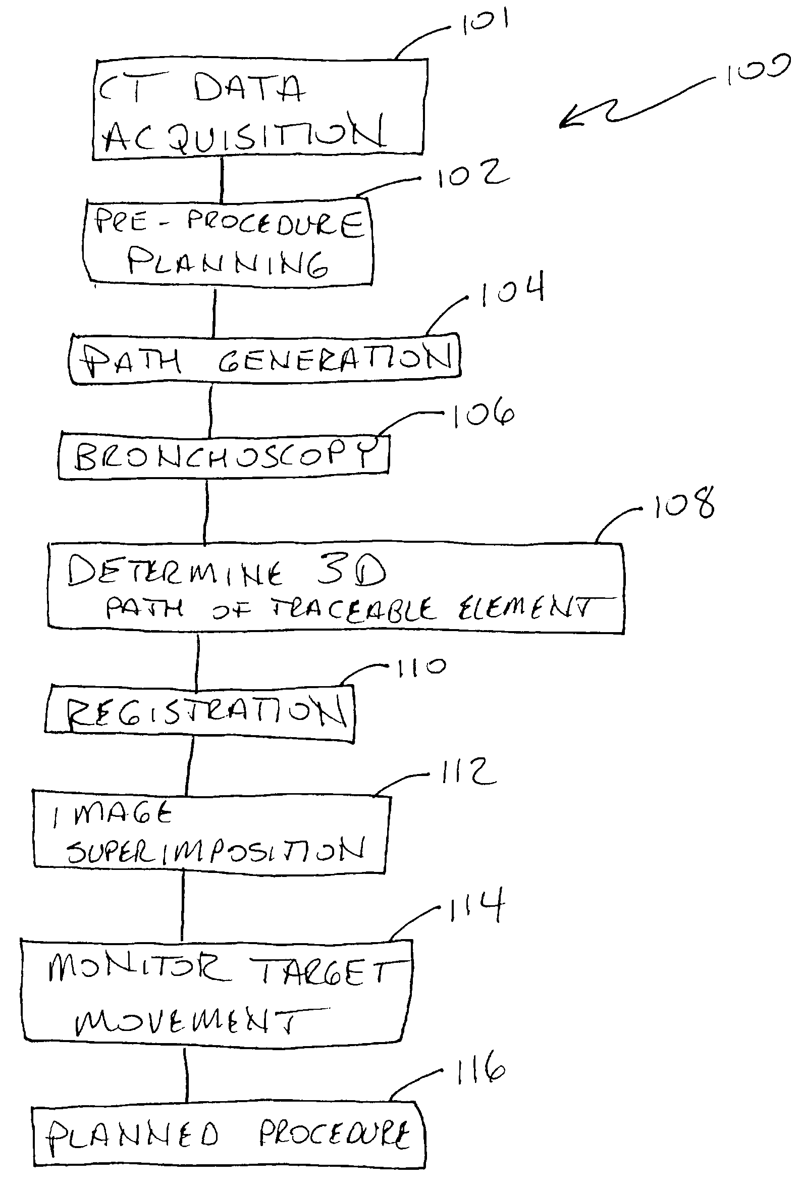
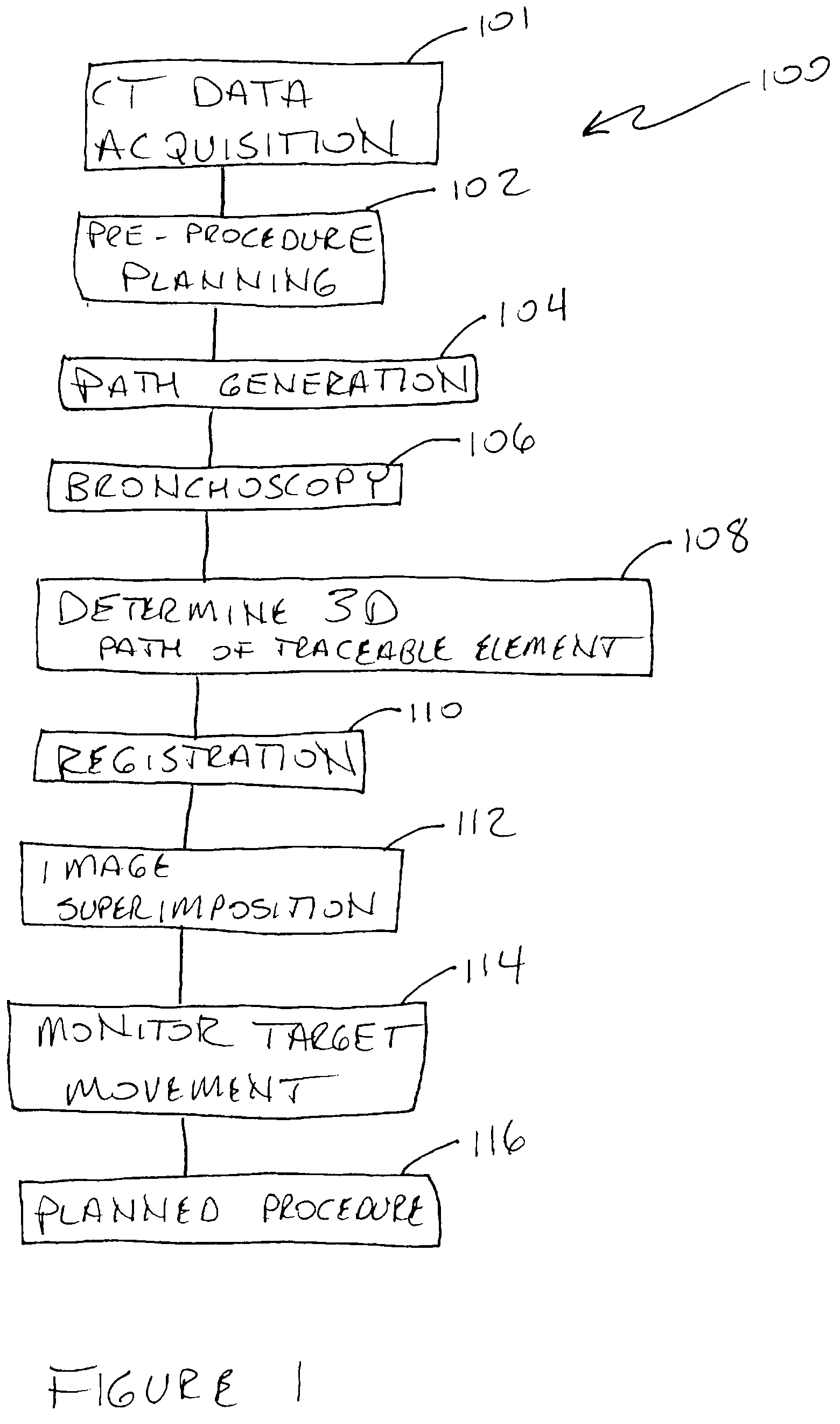
[0038]Referring now to FIG. 1, there is shown a flowchart that illustrates a method 100 of the present invention.

[0039]At 101 of the method 100, CT data is acquired and transformed into a 3D CT volume, which will be used during the procedure in combination with the real-time X-ray (e.g., fluoroscopic) data. This CT data may even be low-dose CT that is later enhanced with fluoroscopic data, if necessary. Enhancement with fluoroscopic data will be explained in more detail below.

[0040]At 102 of the method 100, the practitioner, such as a physiologist for example, performs pre-procedure planning on the CT data acquired at 101, during which he or she marks each point of interest (e.g., a suspicious lesion) and its dimensions. This procedure may be performed manually or semi-automatically, such as when the points of interest are automatically identified by computer software.

[0041]Once the point of interest is marked, at 104 the recommended path to the point of interest area inside the lun...


PUM

PropertyMeasurementUnit
areaaaaaaaaaaa
CTaaaaaaaaaa
radiopaqueaaaaaaaaaa

Abstract

Real-time, enhanced imaging of remote areas, too minute for CT imaging, is made possible through a probe having a radiopaque tip as well as radiopaque volume markers. When deployed, the markers outline the space containing the tip such that both the tip and the volume containing the tip are viewable on a fluoroscope. This device may be used in conjunction with or independently of 3-D volumes created from CT scans and 3-D tip sensors.

Description

RELATED APPLICATIONS[0001]This application claims priority to U.S. Provisional Application Ser. No. 60 / 908,126 filed Mar. 26, 2007 entitled CT-Enhanced Fluoroscopy which is hereby incorporated by reference.BACKGROUND OF THE INVENTION[0002]The various inventions disclosed herein relate generally to the superimposed presentation of relatively low-resolution or low-quality images, acquired in real time, onto relatively high-resolution or high-quality images acquired preoperatively.[0003]Conventional fluoroscopy is widely used during medical procedures as a visualization and validation imaging tool for guiding medical instruments inside the human body. Although medical instruments like catheters, biopsy tools, etc., are clearly visible on a fluoroscopic picture, organic features such as soft tissue, blood vessels, suspicious tumor lesions etc., are quite transparent and hard to identify with conventional fluoroscopy. As such, frequently a higher quality diagnostic image is acquired, suc...

Claims


Application Information

Patent Timeline
Patent Type & Authority Applications(United States)
IPC IPC(8): A61B5/04A61M25/00
CPCA61B6/12A61B6/481A61B6/487A61B6/5235A61M25/0045A61M25/0082A61M25/0108A61M31/005A61M2025/0096A61M2025/0681A61B6/032
Inventor AVERBRUCH, DORIAN
Owner TYCO HEALTHCARE GRP LP
Why Eureka
Try Eureka