Proximally Self-Locking Long Bone Prosthesis

a long bone prosthesis and self-locking technology, applied in the field of medical implants, can solve the problems of joint cartilage damage, mechanical pain, eventual destruction of joint cartilage, etc., and achieve the effects of improving the sealing, maintaining the flexibility of the diaphysis, and improving the sealing

Inactive Publication Date: 2008-10-23
ARTHREX +1
View PDF54 Cites 32 Cited by
  • Summary
  • Abstract
  • Description
  • Claims
  • Application Information

AI Technical Summary

Benefits of technology

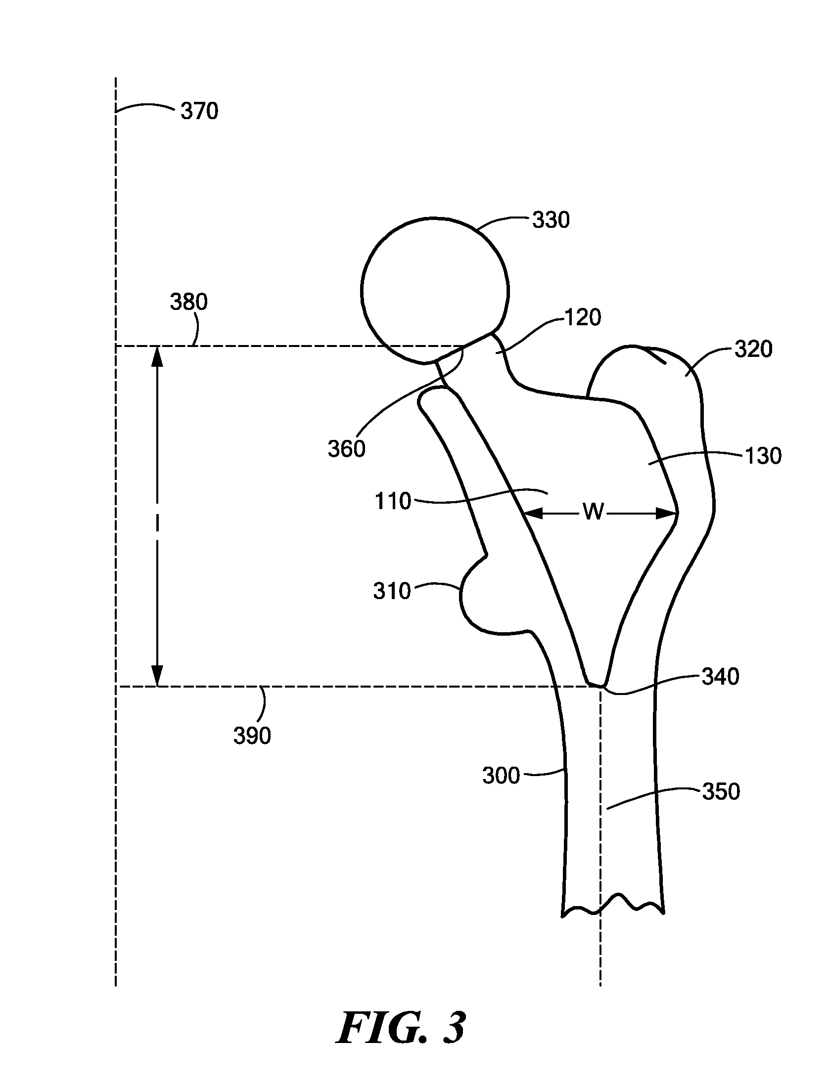
[0017]The locking may create a seal sufficient to exclude particles and debris from entering the junction. Such seal may be improved by positioning a deformable gap-filling material at the interface of the bone-locking portion of the prosthesis and the inner surface of the aperture so that upon the expanding of the bone-locking portion, the gap-filling material is securely held in the junction. The bone may be a femur, the prosthesis a femoral implant, and the majority of the locking force applied to a region of the bone no more distal than the most distal point of the lesser trochanter. The majority of the locking force may be applied to the calcar femorale. According to an embodiment of the invention, the prosthesis may extend into the aperture by less than or equal to 5 inches.
[0018]The shape memory material may be Nitinol. The shape memory material may expand radially by one of less than 8%, 5% and 1%. The flexibility of the diaphysis may be maintained by using a prosthesis with a truncated shaft. The shaft may be inserted so as to not extend into the diaphysis of the bone. The flexibility of the diaphysis may be maintained by using a prosthesis with a distal shaft region that includes a material having a flexibility greater than that of stainless steel so as to prevent stress shielding. The method may include positioning a deformable gap-filling material at the interface of the bone-locking portion of the prosthesis and the inner surface of the aperture. Rotation of the prosthesis after implantation may be prevented by preparing an eccentric aperture and using a prosthesis with a complementary eccentric cross-section. Rotation of the prosthesis after implantation may be prevented by using an aperture that includes a plurality of facets and the bone-locking portion includes a plurality of corresponding facets. Rotation of the prosthesis after implantation may be prevented by using a prosthesis that includes a bone locking portion with a barb, tooth, tang, flute or rib. The bone-locking portion may be characterized by a cross-section, the majority of which is composed of shape-memory material.

Problems solved by technology

Damage to a joint of a patient may result from a variety of causes, including osteoarthritis, osteoporosis, trauma, and repetitive overuse.
Bare bone on the head of the femur grinding against the bone of the pelvic socket causes mechanical pain.
Fragments of cartilage floating in the joint may cause inflammation in the joint lining, which may also cause pain.
The cause is not known; however, it is known that the condition leads to an eventual destruction of the joint cartilage.
Bone next to the cartilage is also damaged; it becomes very soft, frequently making the use of an un-cemented implant impossible.
This dead bone can not stand up to the stresses of walking.
As a result, the femoral head collapses and becomes irregular in shape.
The joint then becomes more painful.
The most common causes of osteonecrosis are excessive alcohol use and excessive use of cortisone-containing medications.
Undesirably, cemented implants often loosen, causing pain and requiring subsequent surgeries.
In addition, the great disparity in the stiffness of a metallic prosthesis and the surrounding bone reduces bending displacements, changing the bending moment distribution in the surrounding bone.
The elongated stem may provide for accelerated integration of the prosthesis and an early recovery, but potentially at the expense of long-term stability.
Proximal bone resorption, along with a levering effect of a long stem, may cause loosening of the prosthesis over time.
An additional source of implant failure results from acetabular wear particles, which induce an inflammatory response in the patient.
The resulting chronic inflammation may cause bone loss through osteolysis.
A further source of cemented implant failure is through degradation of the cement over the course of several decades.
This procedure carries a risk of fracturing the bone, which is estimated by some sources to be in the range of 1-3%.
However, because of inherently lower primary (initial) stability, these stemless implants may require a longer recovery period than conventional stemmed implants and patients must limit weight bearing (e.g., by using crutches) during recovery.
The success of a hip replacement can be adversely affected by periprosthetic infection, which can have immense financial and psychological costs.
Despite these measures, it is believed that deep infection still occurs after 1 to 5 percent of joint replacements.
A tight interference fit between the implant and femoral bone, however, may undesirably scrape and / or squeegee off any drugs applied to the surface of the implant stem.
At least one study found that Nitinol wire has a mode of failure due to bending and compression that is not found in other materials such as austenitic stainless steel.

Method used


Image

  • Proximally Self-Locking Long Bone Prosthesis
  • Proximally Self-Locking Long Bone Prosthesis
  • Proximally Self-Locking Long Bone Prosthesis

Examples


example 1

Finite Element Modeling of a Long-Stemmed Implant

[0073]A computational model of a long-stemmed Nitinol prosthesis was created using finite element modeling techniques. The results warn that long-stemmed prosthetics with Nitinol stems may be susceptible to bending-induced fracture.

[0074]FIGS. 9a and 9b show a finite element model geometries used and designated as “Hip A” and “Hip B” respectively. The material properties for the finite element analyses were assumed to be linear elastic and isotropic. CoCrMo and Nitinol used in these analyses were assumed to follow Hooke's Law, and frictional forces could be neglected since the applied force was much higher than the frictional forces. All finite element models were assumed to be linear and un-cemented. The force(s) transmitted from walking were assumed to be transmitted from the femur into the implant, where the force then was transmitted to the ball. From there, the force was then transmitted into the liner and cup. The force transmit...

example 2

Finite Element Modeling of an Implant According to FIG. 1a

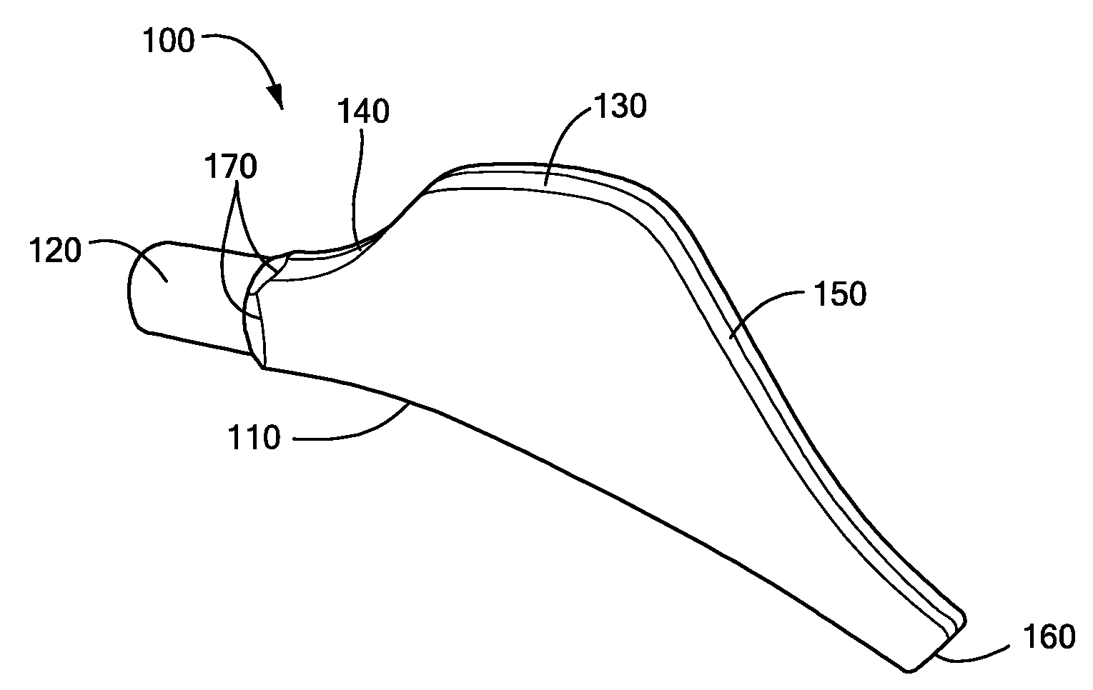
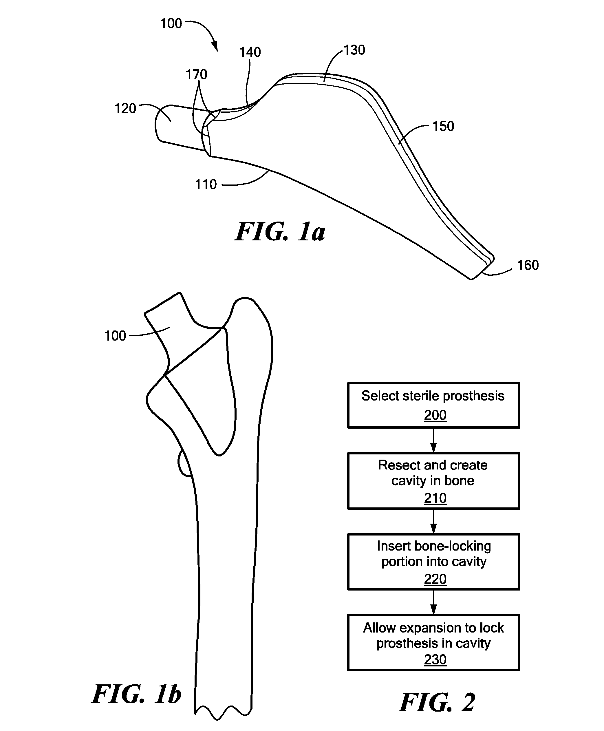
[0081]To confirm the hypothesis that a short-stemmed Nitinol prosthesis 100 with a lateral flare according to FIG. 1a would be sufficiently robust, further finite element modeling was performed to simulate the fatigue endurance strength properties of a short-stemmed prosthesis. A quasi-static analyses was performed with the commercial finite element analysis (FEA) code ABAQUS / Standard version 6.5-1. Three dimensional elements and a large displacement formulation were used. Two material models were used for this report: the first was a Nitinol material model assuming a superelastic response with an Af temperature of 30° C. and a typical stainless steel material with approximately 20% cold work was chosen as a baseline for comparison. Two finite element models were created to examine the effect of mesh refinement on the accuracy of the solution. The number of degrees of freedom for the base model and the fine model were 44853 ...


PUM

PropertyMeasurementUnit
lengthaaaaaaaaaa
elastic moduliaaaaaaaaaa

Abstract

A method for arthroplasty includes using a self-locking prosthesis that has a member structured to transfer a load produced by the weight of a patient to a bone. An expandable bone-locking portion that is integral to the member includes a shape-memory material and expands to produce a locking force. A portion of the bone is removed to form an aperture in the bone. The bone-locking portion is inserted into the aperture, and a temperature increase causes a change from a contracted state to an expanded state resulting in expansion of the bone-locking portion so as to contact the inner surface. The expanding is sufficient to create a locking force at the junction between the inner surface and the bone-locking portion of the prosthesis and the majority of the locking force is applied at or above the metaphysis. The length / width ration of the prosthesis may be less than or equal to 5. The resulting reconstructed long-bone may have improved primary and long-term stability.

Description

CROSS REFERENCE TO RELATED APPLICATIONS[0001]This application for U.S. patent is a Continuation Application of and claims priority from U.S. patent application Ser. No. 12 / 054,678, filed Mar. 25, 2008 and thereby claims priority from Provisional U.S. Patent Application Ser. No. 60 / 919,969, filed Mar. 26, 2007, Attorney Docket 3198 / 104, Confirmation No. 2499; Provisional U.S. Patent Application Ser. No. 60 / 911,427, filed Apr. 12, 2007, Attorney Docket 3198 / 108, Confirmation No. 1426; Provisional U.S. Patent Application Ser. No. 60 / 911,633, filed Apr. 13, 2007, Attorney Docket 3198 / 109, Confirmation No. 1253; Provisional U.S. Patent Application Ser. No. 60 / 943,199, filed Jun. 11, 2007, Attorney Docket 3198 / 110, Confirmation No. 9492; and Provisional U.S. Patent Application Ser. No. 60 / 991,952, filed Dec. 3, 2007, Attorney Docket 3198 / 111, Confirmation No. 4770, the disclosures of which are hereby incorporated herein in their entirety.TECHNICAL FIELD[0002]The invention generally relate...

Claims


Application Information

Patent Timeline
Patent Type & Authority Applications(United States)
IPC IPC(8): A61F2/36A61F2/30
CPCA61F2/30742A61F2/30767A61F2/30771A61F2/3094A61F2/30942A61F2/36A61F2/3662A61F2/367A61F2/3676A61F2/468A61F2002/30014A61F2002/30018A61F2002/30019A61F2002/30039A61F2002/30092A61F2002/30093A61F2002/30153A61F2002/30579A61F2002/30604A61F2002/30616A61F2002/30682A61F2002/30685A61F2002/30769A61F2002/30891A61F2002/30892A61F2002/30909A61F2002/30955A61F2002/30968A61F2002/3611A61F2002/3625A61F2002/365A61F2002/3664A61F2210/0014A61F2210/0019A61F2230/0019A61F2250/0018A61F2250/0029A61F2250/0042A61F2250/0048A61F2310/00017A61F2310/00023A61F2310/00029A61F2310/00407A61F2310/00598A61F2310/00796A61F2310/0097A61F2002/30878
Inventor FONTE, MATTHEW V.
Owner ARTHREX
Why Eureka
Try Eureka