Method of detecting, locating, and classifying lightning

Inactive Publication Date: 2008-10-23
TOA SYST
View PDF13 Cites 29 Cited by
  • Summary
  • Abstract
  • Description
  • Claims
  • Application Information

AI Technical Summary

Benefits of technology

[0023]The invention concerns a method for identifying a source location of lightning. The method begins by positioning three or more monitoring stations at different spaced apart geographic locations. Each monitoring station includes a matched filter receiver. Responsive to a lightning occurrence, a signal is received at each of the matched filter receivers. The method continues in each matched filter receiver with communicatin

Problems solved by technology

Currently, lightning discharges are detected using envelope detection or amplitude threshold techniques which are limited to detection above the noise level.
However, VHF detection systems must be able to process information at extremely high data rates, as VHF pulse emissions in IC lightning occur approximately one tenth of a millisecond apart.
Additionally, VHF systems can only detect lightning events that have direct line of sight to the sensor.
However, this system is further restricted to line of sight between the sensors and the central analyzer as it uses a real time microwave communication system.
Analog sensors operating at LF and VLF frequencies are difficult to tune for both CG and IC lightning discharges.
Optimizing the gain of one of these sensors to detect IC events often causes the sensor to become saturated with the much greater energy of nearby CG lightning discharges.
Therefore, it is customary to adjust the gain to accommodate both types of field signals, reducing a sensor's ability to detect IC events.
As distant IC lightnin

Method used


Image

  • Method of detecting, locating, and classifying lightning
  • Method of detecting, locating, and classifying lightning
  • Method of detecting, locating, and classifying lightning

Examples


Embodiment Construction

[0060]The invention will now be described more fully with reference to the accompanying drawings, in which illustrative embodiments of the invention are shown. This invention may, however, be embodied in many different forms and should not be construed as limited to the embodiments set forth herein. For example, the present invention can be embodied as a method, a data processing system, or a computer program product. Accordingly, an embodiment of the present invention can be entirely in the form of hardware, or entirely in the form of software, or in the form of hardware in combination with software.

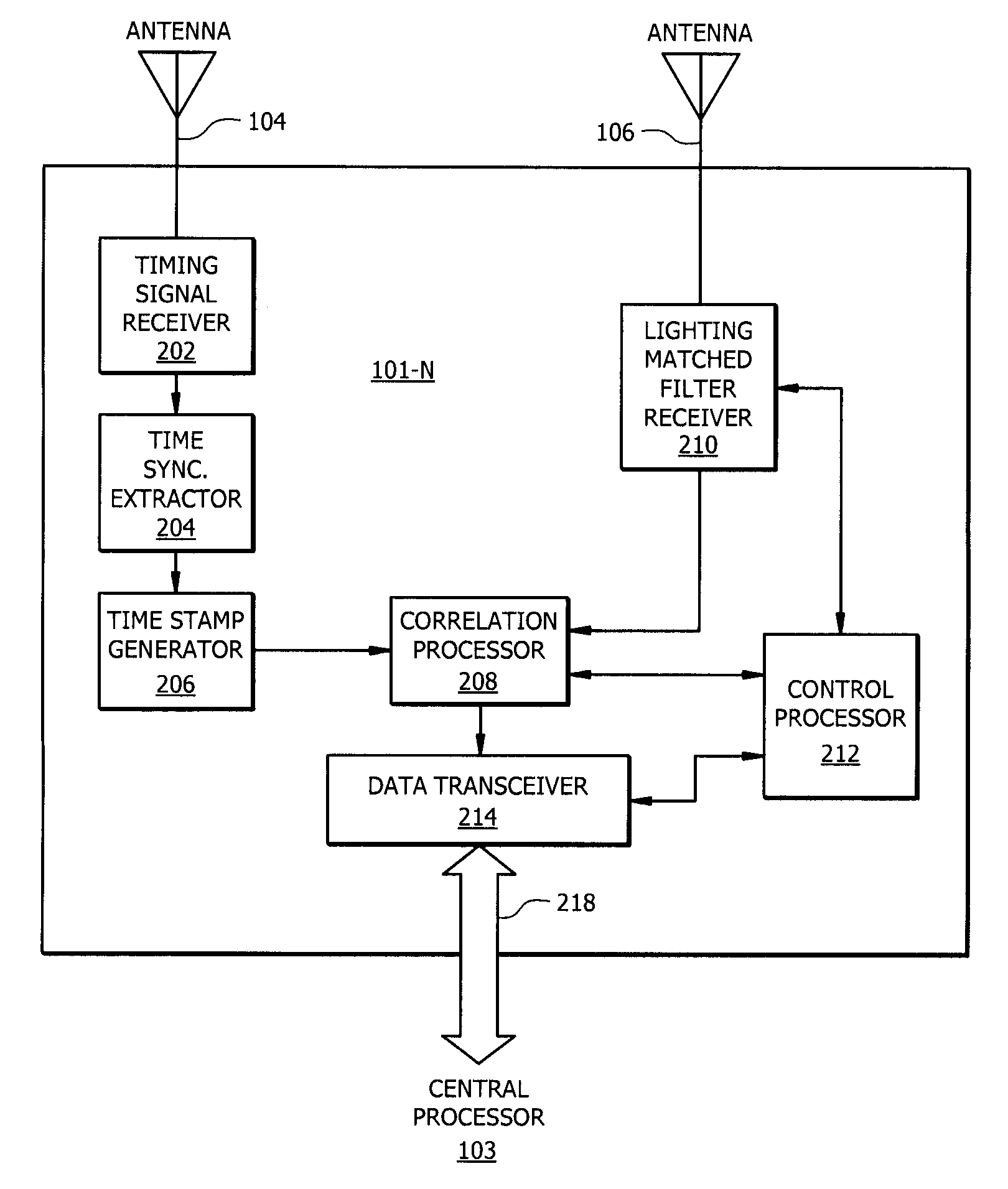
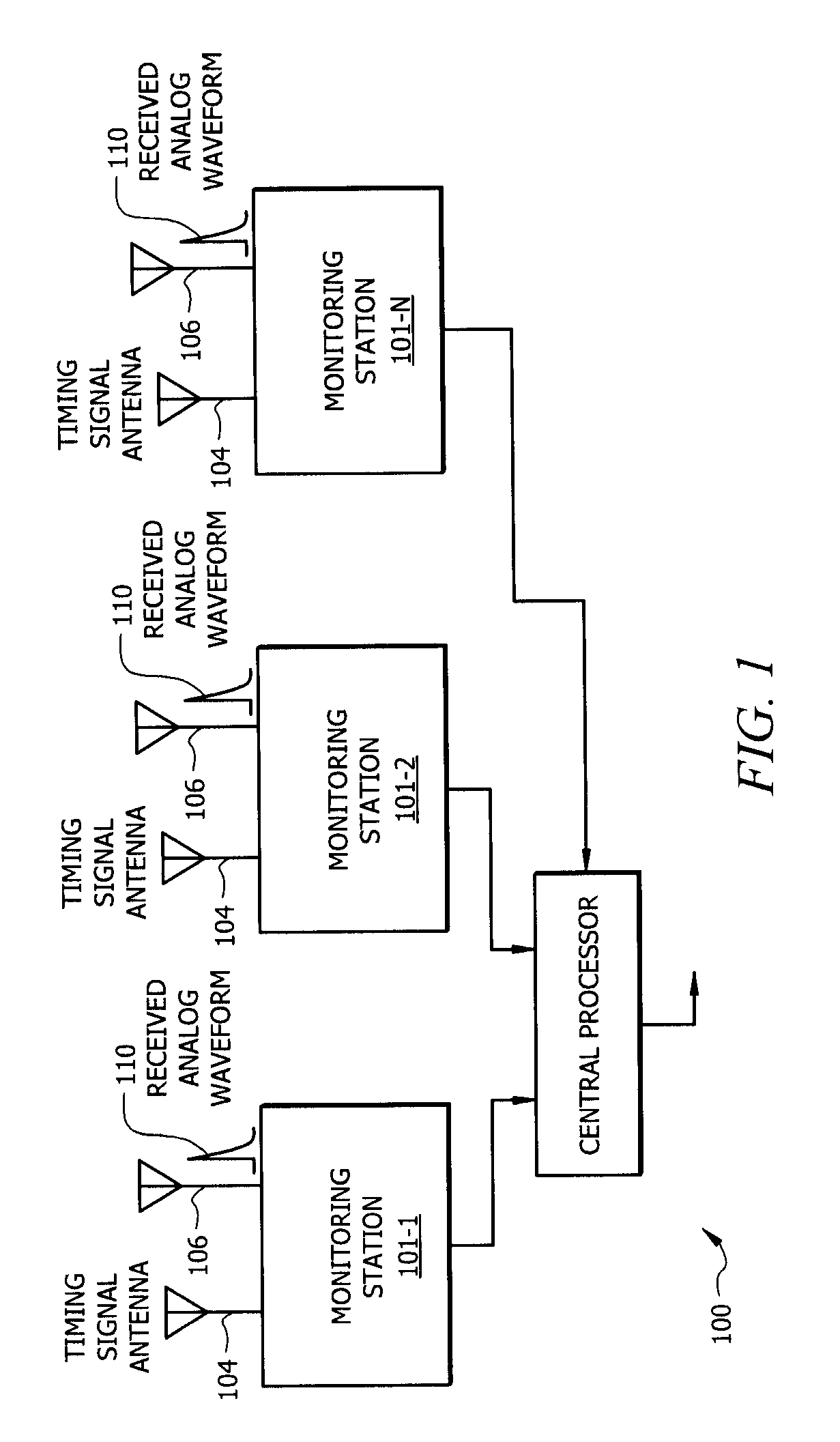
[0061]Referring to FIG. 1, there is shown a block diagram which conceptually illustrates the operation of a time difference of arrival (TDOA) type system 100 for locating a source of an electromagnetic signal having a particular wave form. The system includes three or more monitoring stations 101-1, 101-2, 101-N positioned at different spaced apart geographic locations. In FIG. 1 only t...


PUM


Abstract

There is discloses a new method for identifying an electromagnetic signal having a known waveform. The method includes using a lightning matched filter receiver having a bank of filters matched to nominal but arbitrary lightning waveforms for detecting lightning. The use of a lightning matched filter receiver facilitates detection of lightning discharges below the noise level. Positioning three or more monitoring stations at different spaced apart geographic locations where each monitoring station has a lightning matched filter receiver where the filters are matched to nominal but arbitrary lightning waveforms can be used to detect and determine the location of a lightning discharge.

Description

CROSS REFERENCES TO RELATED APPLICATIONS [0001]This application claims priority to U.S. Patent Application Ser. No. 60 / 912,287, filed Apr. 17, 2007, which is hereby incorporated by reference in its entiretyBACKGROUND OF THE INVENTION[0002]1. Statement of the Technical Field[0003]This invention relates generally to a lightning discharge and more particularly to an improved method and apparatus for detecting, classifying, and locating lightning.[0004]2. Description of the Related Art[0005]A lightning discharge is a natural phenomenon that produces a non-cooperative electrical field waveform which varies drastically in intensity and duration. The lightning discharge, in its entirety, whether it strikes the ground or not, is usually termed a lightning flash or just a flash. A lightning discharge that involves an object on the ground or in the atmosphere is sometimes referred to as a lightning strike. The terms stroke or component stroke apply only to components of cloud to ground discha...

Claims


Application Information

Patent Timeline
IPC IPC(8): G01W1/00
CPCG01W1/16
Inventor DAVIS, ROBERT T.BENT, RODNEY B.
Owner TOA SYST
Why Eureka
Try Eureka