Sytem and a Method for Motion Tracking Using a Calibration Unit

a technology of motion tracking and calibration unit, applied in the field of motion tracking system, can solve the problems of limiting the working area of the subject, affecting the accuracy of the measurement, so as to achieve the effect of increasing the accuracy

Active Publication Date: 2008-10-23
XSENS HLDG BV
View PDF7 Cites 79 Cited by
  • Summary
  • Abstract
  • Description
  • Claims
  • Application Information

AI Technical Summary

Benefits of technology

[0019]It is an object of the invention to provide a system and a method for motion tracking wherein the calibration step, providing data on at least orientation of the OMU on a body portion and relative proportions between the body portions constituting a sequence interconnected by joints, is performed with increased accuracy.

Problems solved by technology

The set-up of external emitters or cameras limits the working area where the subject can be captured and impedes many applications.
It is a disadvantage of the known system and method for obtaining the orientation of the OMU with respect to the body portions as well as the relative distances between joints in that substantial inaccuracies occur due to errors in palpation or errors in acquiring and sustaining a static pose.
Further, the known methods lacks subject specificity because only a few measures are taken and the joint position can not be measured directly, but must be derived using regression equations based on average human dimensions.
The known methods for obtaining necessary data for calibration when using an IMU as OMU are particularly disadvantageous because as an additional requirement the subject has to stand in a known pose with respect to gravity as well as with respect to a local magnetic field.
This latter condition places an extra burden on the subject.

Method used


Image

  • Sytem and a Method for Motion Tracking Using a Calibration Unit
  • Sytem and a Method for Motion Tracking Using a Calibration Unit
  • Sytem and a Method for Motion Tracking Using a Calibration Unit

Examples


Embodiment Construction

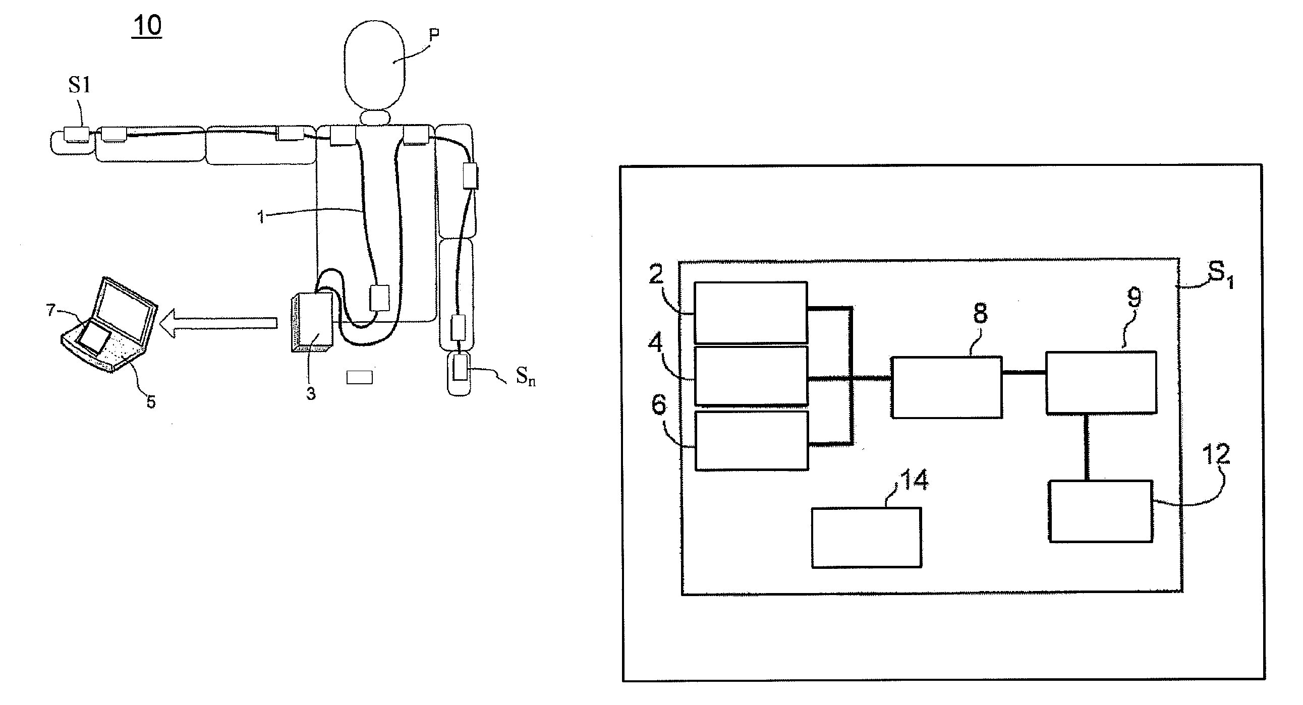
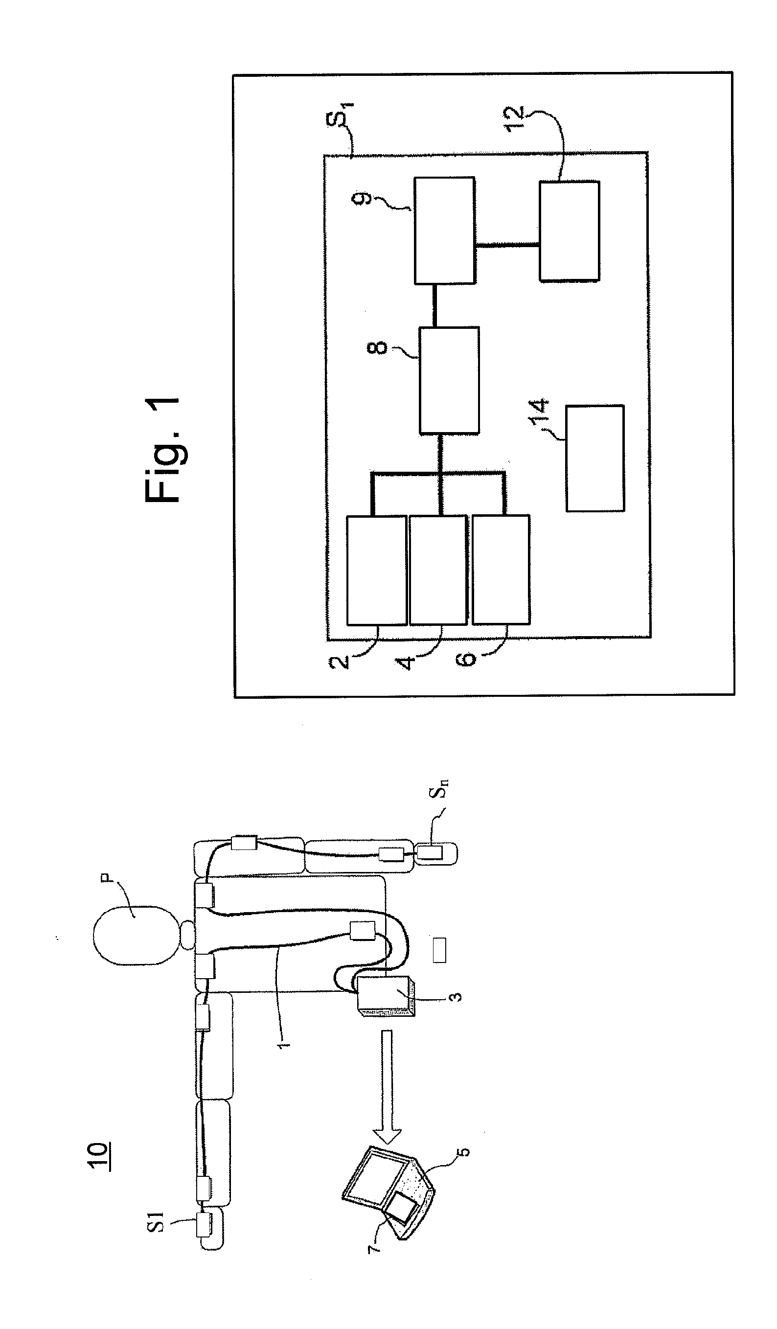
[0064]FIG. 1 presents in a schematic way an embodiment of a motion capture systems according to the invention. The system 10 comprises of a number of orientation measurement units S1, . . . , Sn, notably inertial and magnetic sensor modules comprising suitable sensors, like 3D gyroscope 2, 3D accelerometer 4, 3D magnetic sensor 6. Notably, linear accelerometers possibly combined with magnetometers can be used for orientation measurement devices. Preferably, the orientation measurement units are arranged for each body segment to be tracked. The sensors may be connected to a bus system 3 which is arranged to provide the power supply for an sensors, synchronization of data sampling and, preferably, wireless transmission of all sensor and processed data to an external computer 7 or to any suitable logging device. The bus system 3 may contain one or more strings to which sensor modules are connected. Preferably, each sensor comprises a sensor sampling module 8, a digital signal processor...


PUM


Abstract

The invention relates to motion tracking system (10) for tracking a movement of an object (P) in a three-dimensional space, the said object being composed of object portions having individual dimensions and mutual proportions and being sequentially interconnected by joints the system comprising orientation measurement units (S1, S3, . . . SN) for measuring data related to at least orientation of the object portions, wherein the orientation measurement units are arranged in positional and orientational relationships with respective object portions and having at least orientational parameters; a processor (3, 5) for receiving data from the orientation measurement units, the said processor comprising a module for deriving orientation and/or position information of the object portions using the received data and a calibration unit (7) arranged to calculate calibration values based on received data and pre-determined constraints for determining at least the mutual proportions of the object portions and orientational parameters of the orientation measurement units based on received data, pre-determined constrains and additional input data. The invention further relates to a method for tracking a movement of an object, a medical rehabilitation system and an animation system.

Description

FIELD OF THE INVENTION[0001]The invention relates to a motion tracking system for tracking a movement of an object in a three-dimensional space, the said object being composed of object portions having individual dimensions and mutual proportions and being sequentially interconnected by joints, the system comprising:[0002]orientation measurement units for measuring data related to at least an orientation of the object portions, wherein the orientation measurement units are arranged in positional and orientational relationships with respective object portions having at least orientational parameters;[0003]a processor for receiving data from the orientation measurement units, the said processor comprising a module for deriving orientation and / or position information of the object portions using the received data.[0004]The invention further relates to a method for tracking a movement of an object being composed of object portions having individual dimensions and mutual proportions and ...

Claims


Application Information

Patent Timeline
Patent Type & Authority Applications(United States)
IPC IPC(8): G01C25/00
CPCA61B5/1038A61B5/1114A61B5/112A61B5/1121A61B5/1122A61B5/1126A61B5/4528A61B5/7207A61B2560/0223A61B2562/0219B25J9/1694G05B2219/37388G05B2219/42337A61B5/6804A61B2562/046G06F3/011
Inventor LUINGE, HENDRIK JOHANNESROETENBERG, DANIELSLYCKE, PER JOHAN
Owner XSENS HLDG BV
Why Eureka
Try Eureka