
Riding lawnmower vehicle

a lawnmower and riding technology, applied in the direction of electric propulsion mounting, electric devices, transportation and packaging, etc., can solve the problems of inability to independently drive two rear wheels, and ineffective use of vehicles, so as to reduce the total number of components, reduce costs, and efficient cooling

Active Publication Date: 2008-10-30
KANZAKI KOKYUKOKI MFG
View PDF19 Cites 80 Cited by
  • Summary
  • Abstract
  • Description
  • Claims
  • Application Information

AI Technical Summary

Benefits of technology

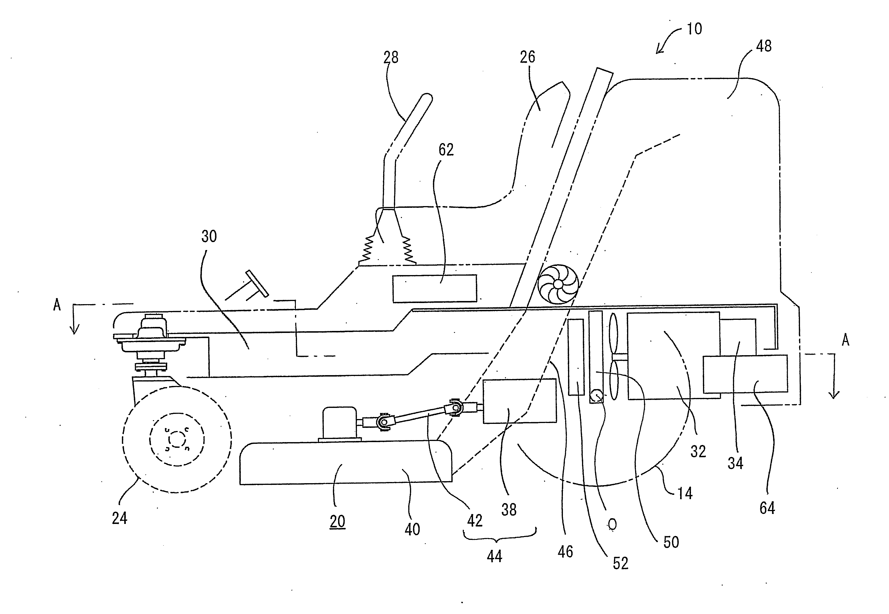
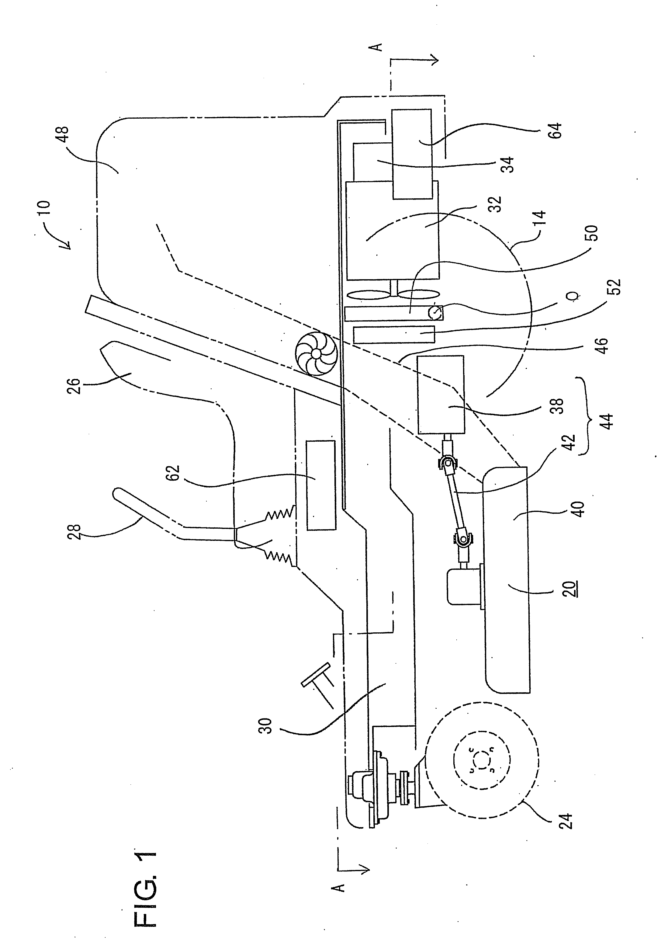
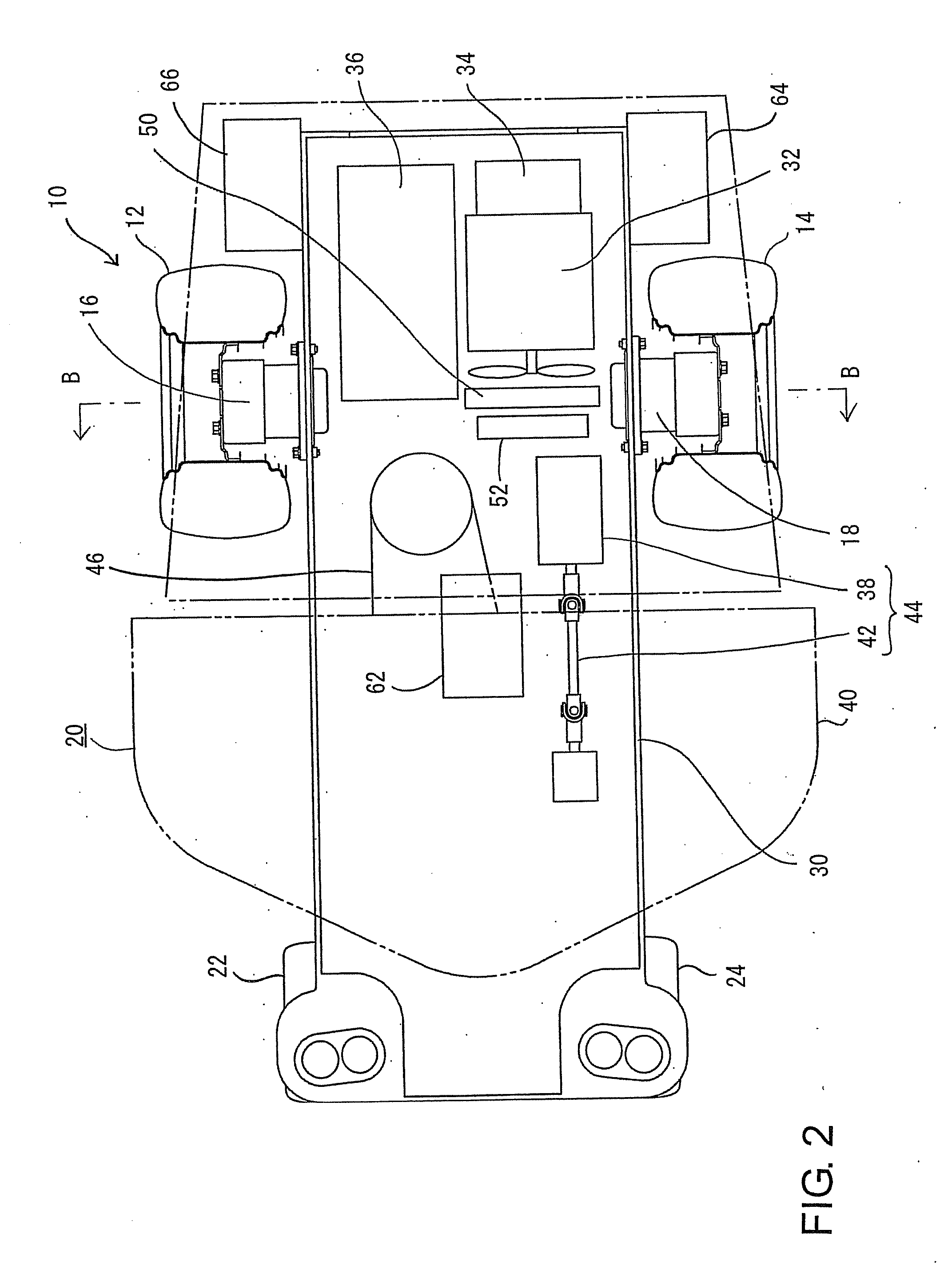
[0022]In a first aspect of the present invention, exemplary embodiments are directed to a riding lawnmower vehicle that can enhance the efficiency of use of the limited space available on a vehicle.

Problems solved by technology

As such, it is possible that the lower space of the vehicle may not be effectively used and that, thus, a margin for improvement in the efficiency of use of a limited space is available, if required.
Furthermore, as there is no description regarding the positional relationship between the lower end of the battery (or the fuel cell) and the rotation center axis of the front wheels (drive wheels), the lower space of the vehicle may not be effectively used.
According to the riding lawnmower vehicle discussed in U.S. Pat. No. 3,732,671, although the battery overlaps the rear wheels (drive wheels) in the width direction of the vehicle, the two rear wheels cannot be independently driven.
Furthermore, because the lower end of the battery is positioned higher than the rotation center axis of the rear wheels (drive wheels), the lower space of the vehicle may not be effectively used.

Method used


Image

  • Riding lawnmower vehicle
  • Riding lawnmower vehicle
  • Riding lawnmower vehicle

Examples


tenth exemplary embodiment

[0206]FIG. 17 illustrates a cross-sectional view of the mower 20, the engine 32, and the generator 34 according to a tenth exemplary embodiment of the present invention that relates to the first aspect. The lawnmower vehicle according to this embodiment includes the engine 32 that can drive the generator 34. The engine 32 has a rotational shaft extending in the vertical direction. A first drive pulley 108 and a second drive pulley 110 are fixed on the rotational shaft of the engine 32. One belt 114 is wound around the first drive pulley 108 and the driven pulley 112 fixed to the generator 34. The driving force of the engine 32 can be transmitted to the generator 34 via the belt 114. Furthermore, another belt 96 is wound around the second drive pulley 110 and the driven pulley 92 fixed to the drive shaft of the mower blade 90. The driving force of the engine 32 can be transmitted to the mower 20 via the belt 96. Because the remaining configuration and actions are the same as in the a...

eleventh exemplary embodiment

[0207]FIG. 18 illustrates a cross-sectional view of the mower 20, the engine 32, and the generator 34 according to an eleventh exemplary embodiment of the present invention that relates to the first aspect. The lawnmower vehicle according to this embodiment includes the engine 32 capable of driving the generator 34. The engine 32 has a rotational shaft extending in the horizontal direction. The generator 34 is fixed to one side of the engine 32, so that the driving power of the rotational shaft of the engine 32 can be transmitted to the generator 34.

[0208]A drive pulley 116 is fixed on the rotational shaft of the engine 32. The driven pulley 92 is fixed on the drive shaft of the mower blade 90. A bevel gear unit 118 is fixed on the main frame 30 (refer to FIGS. 1 and 2) between the engine 32 and the mower 20. The bevel gear unit 118 includes a horizontal shaft and a vertical shaft which are rotatably supported by a casing. One belt 96 is wound around a pulley 120 fixed to the horizo...

twelfth exemplary embodiment

[0211]FIG. 19 illustrates a pedal powered generator 124 according to a twelfth exemplary embodiment of the present invention that relates to the first aspect that is installable on the lawnmower vehicle of the first exemplary embodiment described with reference to FIGS. 1 and 2. The lawnmower vehicle according to this embodiment does not include the engine 32 and the generator 34 (refer to FIGS. 1 and 2) described in the first exemplary embodiment. The pedal powered generator 124 includes a support base 126 positioned near legs of an operator sitting on the driver's seat 26 (refer to FIG. 1), a crank shaft 128 rotatably supported by the support base 126, and pedals attached to both ends of the crank shaft 128.

[0212]FIG. 20 is a block diagram illustrating part of a lawnmower vehicle including the pedal powered generator 124 according to the twelfth exemplary embodiment. As illustrated in FIG. 20, a generator 130 capable of generating electricity in accordance with rotation of the cra...


PUM


Abstract

A riding lawnmower vehicle includes two main drive wheels, at least one caster wheel, an electric traction motor, an internal combustion engine, a generator driven by the internal combustion engine, and a lawnmower. The electric energy generated by the generator can be supplied directly or via an electric accumulator to the electric traction motor. The main drive wheels are independently driven by the electric traction motor, which can operate as a traction power source. When viewed from one end to the other end in the width direction of the vehicle, the internal combustion engine and a secondary battery operable as the electric accumulator overlap each other, and the main drive wheels overlap at least a part of at least one of the internal combustion engine, the generator, the secondary battery, a fuel cell, a capacitor, an inverter, a cooling device, a mower driving motor, and a grass-collecting duct.

Description

PRIORITY INFORMATION[0001]The present invention claims priority from Japanese Patent Application No. 2007-114744, Japanese Patent Application No. 2007-114745, and Japanese Patent Application No. 2007-114746 all filed Apr. 24, 2007, which are hereby incorporated herein in their entirety.BACKGROUND[0002]1. Technical Field[0003]A first aspect of the present invention relates to a riding lawnmower vehicle including main drive wheels that can be driven by a traction power source and a lawnmower. A second aspect of the present invention relates to a riding lawnmower vehicle that includes a front frame supporting at least two front wheels, a rear frame supporting at least two rear wheels, a joint unit connecting the front frame and the rear frame which cooperatively constitute an articulated vehicle body, a steering apparatus changing a twist angle between the front frame and the rear frame according to an operation amount of an operation unit, and a lawnmower. A third aspect of the presen...

Claims


Application Information

Patent Timeline
Patent Type & Authority Applications(United States)
IPC IPC(8): A01D43/06A01D69/02
CPCA01D34/44A01D34/66A01D34/6806A01D34/78A01D67/00A01D69/02B60K1/04B60K6/46B60K7/0007B60K7/0015B60K17/043B60K17/046B60K17/30B60K17/356B60K2001/003B60K2007/0038B60K2007/0046B60K2007/0061B60L2200/40B60L2220/46B60W2300/156B60Y2200/223Y02T10/6217Y02T10/6265Y02T10/6278Y02P60/14Y02T10/62
Inventor ISHII, NORIHIROSASAHARA, KENGOKOGA, KAZUNARIMATSUURA, JUNEBIHARA, TOMOYUKIMIZUKAWA, KATSUMOTO
Owner KANZAKI KOKYUKOKI MFG
Learn More