Lng Regasification Configurations and Methods

a technology of configuration and gasification, applied in the field of gas processing, can solve the problems of imposing constraints on specific gas components, affecting the quality of gas components, and a substantial fraction of the world lng supply is rich lng with non-compliance with heating values

Inactive Publication Date: 2008-10-30
FLUOR TECH CORP
View PDF14 Cites 37 Cited by
  • Summary
  • Abstract
  • Description
  • Claims
  • Application Information

AI Technical Summary

Benefits of technology

[0011]The present invention is directed to configurations and methods of processing LNG in which the pressure of one portion of the LNG is set to a processing pressure at which LNG processing takes place to thereby generate a processed (typically lean) LNG. The so formed processed LNG may then be further pressurized to a delivery pressure an

Problems solved by technology

As the demand for natural gas in the United States has risen sharply in recent years, the market price of natural gas has become increasingly volatile.
One of the problems with LNG import is that a substantial fraction of the world LNG supply is rich LNG with non-compliant heating values.
California also imposes constraints on specific gas components for compressed natural gas consumption.
Currently, acceptable LNG that meets the California specification is limited to sources such as the Kenai, Alaska LNG, or the Atlantic LNG from Trinidad.
However, there are limits on the maximum amount of nitrogen and inerts that can be introduced to the pipeline gas.
Moreover, dilution with nitrogen often requires an air separation plant to produce the nitrogen, which is costly and produces no other benefit for the facility, and a lean gas source is often not available for blending in a relatively large LNG regasification facility.
However, either heating process is undesirable as fuel gas heaters generate emissions and CO2 pollutants, and seawater heaters require costly seawater systems and also negatively impact the ocean environment.
Furthermore, dilution with nitrogen to control the natural gas heating value is typically uneconomical as it generally requires a nitrogen source (e.g., an air separation plant) that is relatively costly to operate.
While the dilution methods can produce “on-spec” heating values, th

Method used


Image

  • Lng Regasification Configurations and Methods
  • Lng Regasification Configurations and Methods
  • Lng Regasification Configurations and Methods

Examples


examples

Exemplary Calculation of Components in Selected Streams

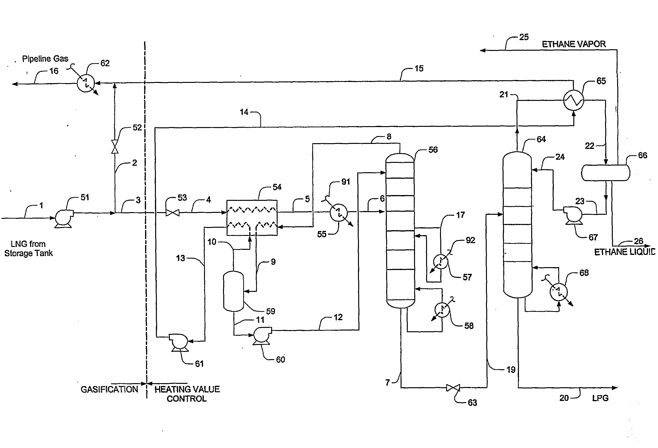
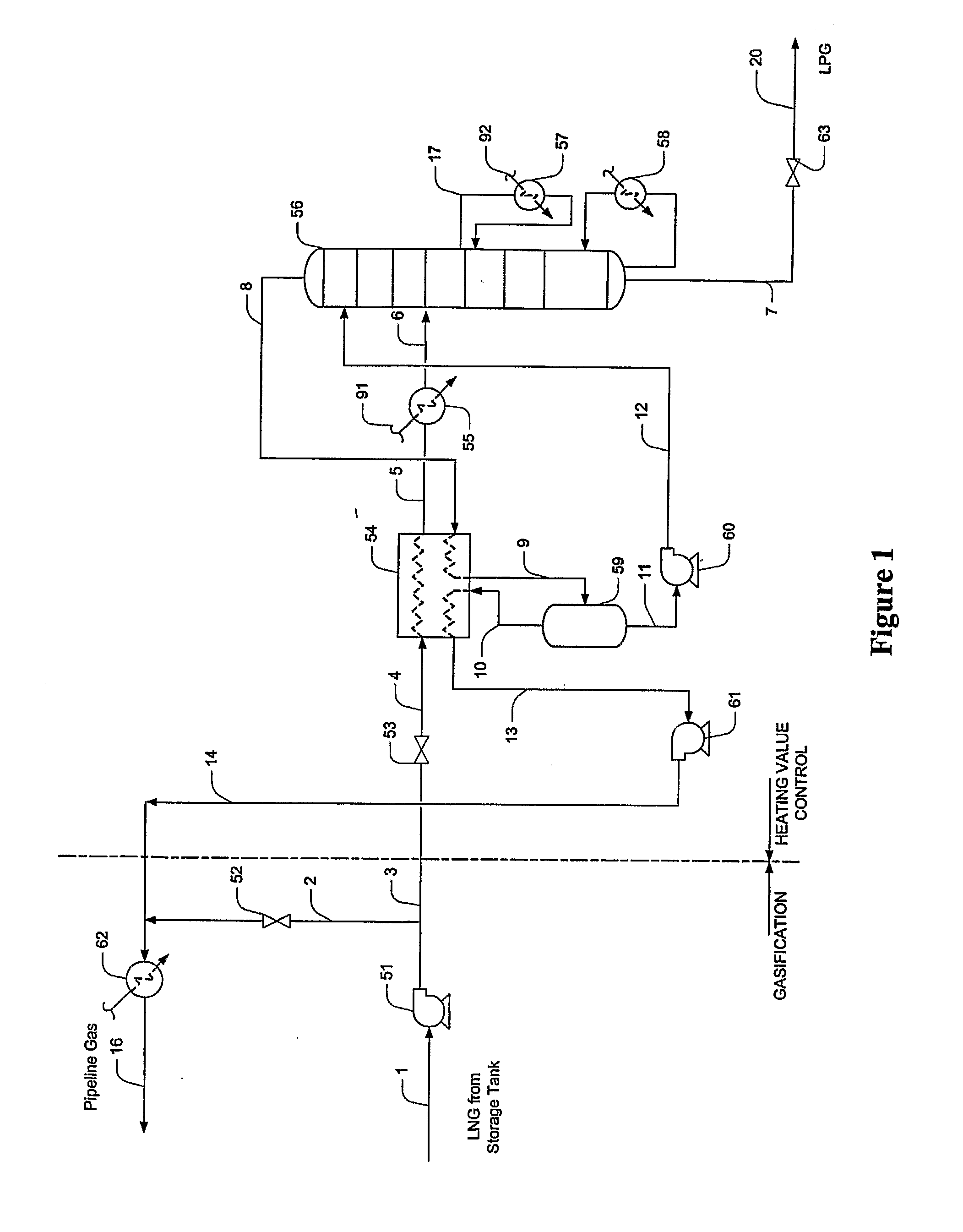
[0056]In an exemplary configuration substantially identical with the plant configuration as shown in FIG. 1, the mol fraction of various components of selected streams were calculated, and the results are listed in Table 1 below. LPG is the C3+ bottom fraction of the demethanizer stream 20, and the pipeline gas is depicted as stream 16.

TABLE 1Com-ponentLNG FeedEthaneLPGPipeline GasN20.00650.00000.00000.0073C10.88160.01760.00000.9878C20.05220.97230.00530.0042C30.03280.00920.54070.0006iC40.00710.00000.12060.0000NC40.01070.00000.18180.0000iC50.00400.00000.06730.0000NC50.00200.00000.03370.0000C6+0.00300.00000.05050.0000Heat1,1531,7502,985999ValueBtu / SCF(HHV)MMscfd5002530450Barrel per218,00016,00021,000181,000day


PUM


Abstract

LNG composition of LNG from a storage tank or other source is modified in a process in which the LNG is pumped to a first pressure and split into two portions. One portion of the pressurized LNG is then reduced in pressure and heavier components are separated from the reduced pressure LNG to thereby form a lean LNG. The lean LNG is then pumped to a higher pressure and combined with the other portion to form a leaner LNG. Preferably, separation is performed using a demethanizer, wherein part of the demethanizer overhead product is condensed to form the lean LNG, while another portion is used for column reflux. In further preferred configurations, ethane recovery is variable and in yet other configurations, propane or ethane can be delivered via a batching pipeline.

Description

[0001]This application claims priority to our copending U.S. provisional patent applications with Ser. Nos. 60 / 584,611, and 60 / 683,181, which were filed Jun. 30, 2004 and May 20, 2005, respectively, and which are both incorporated by reference herein.FIELD OF THE INVENTION[0002]The field of the invention is gas processing, especially as it relates to regasification of liquefied natural gas for heating value control, and recovery or extraction of C2, and C3 plus components for sales.BACKGROUND OF THE INVENTION[0003]As the demand for natural gas in the United States has risen sharply in recent years, the market price of natural gas has become increasingly volatile. Consequently, there is a renewed interest in import of liquefied natural gas (LNG) as an alternative source for natural gas. However, most import LNG has a higher heating value and is richer in heavier hydrocarbons than is allowed by typical North American natural gas pipeline specifications. For example, while some countri...

Claims


Application Information

Patent Timeline
IPC IPC(8): F25J3/00
CPCF25J3/0214F25J2290/10F25J3/0238F25J3/0242F25J2200/02F25J2200/04F25J2200/72F25J2200/74F25J2205/04F25J2215/62F25J2235/60F25J2240/02F25J2245/02F25J2270/02F25J3/0233
Inventor MAK, JOHNNEUMANN, RALPHGRAHAM, CURTHEFFREN, DAN
Owner FLUOR TECH CORP
Why Eureka
Try Eureka