Reconfigurable array with multi-level transmitters

a multi-level transmitter and configuration array technology, applied in the field of ultrasonic systems, can solve the problems of inability to connect several thousand elements to respective pulsers in the system, inability to ergonomically work, and large amount of power, and achieve the effect of small footprint and minimal power expenditur

Active Publication Date: 2008-10-30
GENERAL ELECTRIC CO
View PDF11 Cites 65 Cited by
  • Summary
  • Abstract
  • Description
  • Claims
  • Application Information

AI Technical Summary

Benefits of technology

[0013]Accordingly, there is a need to solve the problem of driving a large number of small ultrasound transducers in a two-dimensional array c

Problems solved by technology

These systems typically are able to drive only about 128-256 channels and consume a large amount of power.
Connecting several thousand elements to respective pulsers in the system is technically not feasible because a cable bundle of coaxial or other wire comprising a sufficient number of conductors for several thousand elements would be too thick and heavy to be ergonomically viable.
Also, a cable that would connect the system pulsers to the transducer elements would present a very large capacitance load compared to the impedance of the two-dimensional array element.
However, it would be prohibitive for a portable system, which would not be able to supply sufficient cooling for the pulsers.
In

Method used


Image

  • Reconfigurable array with multi-level transmitters
  • Reconfigurable array with multi-level transmitters
  • Reconfigurable array with multi-level transmitters

Examples


first embodiment

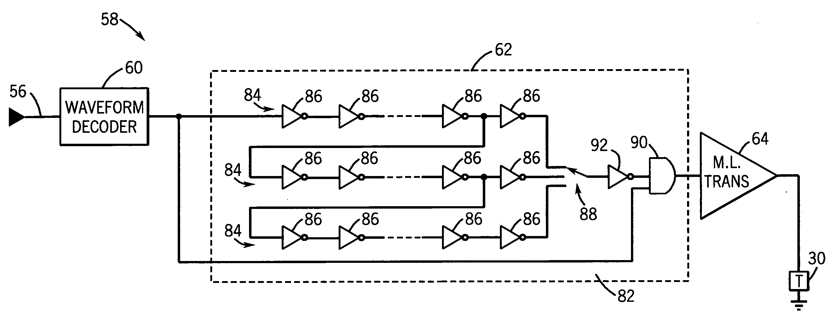
[0038]Referring initially to FIG. 7, the multi-level transmitter cell 58 includes a waveform decoder 60 comprising a comparator 66 and a voltage translator 68. In this embodiment, the comparator 66 acts as a decoder. Further, the output stage 64 includes each of a PMOS and NMOS transistor 70 and 72, respectively, coupled in series between a voltage source and ground. As will be appreciated, while ground is used as a reference, it will be understood that this reference could be replaced by a negative supply equal to or a different value from the positive supply, without altering the functionality of the circuit. The transmitter controller 62 acts like a set point controller such that the output voltage is compared to the input control voltage and any error is used to drive the output to match the control voltage, as will be appreciated by those skilled in the art. It will further be appreciated that the output drive devices are shut off once the desired voltage is reached and are thu...

second embodiment

[0039]FIG. 8 illustrates the multi-level transmitter cell 58. Rather than providing a feedback loop from the output stage 64 to the waveform decoder 60, digital to analog converters (DACs) 74 are employed as the transmitter controller 62 to control the output stage 64 and transmission to the acoustical sub-element 30.

third embodiment

[0040]FIG. 9 illustrates the multi-level transmitter cell 58. In the embodiment illustrated in FIG. 9, the transmitter controller 62 comprises a switch 76 to allow for switching between four gate voltages Vgs1-Vgs4 relative to the high voltage source voltage HVP, depending on the input control waveform. In one embodiment, Vgs1=HVP-0V, Vgs2=HVP-1.0V, Vgs3=HVP-2.5V and Vgs4=HVP-5V, for example. The gate voltage is applied to a resistor loaded output stage 64 comprising a transistor 78 and a resistor 80. The gate of the transistor 78 is controlled by the gate voltage Vgs1. Here the transistor 78 is a high voltage field effect transistor which is used to modulate a current that is fed into the resistor 80. The output voltage across the transducer 30 is that developed across the resistor 80 due to the drive current. Advantageously, an output stage 64, in accordance with this exemplary embodiment may be implemented in a very compact area and will draw a non-negligible current during the t...


PUM


Abstract

An imaging probe having multi-level transmitter cells. The imaging probe includes a plurality of acoustical sub-elements for transmitting and receiving acoustic energy for imaging. Each of the multi-level transmitter cells is arranged along a respective transmitter cell path between a switching matrix and one of the acoustical sub-elements. The multi-level transmitter cells in the probe are capable of producing signals having multiple voltage levels.

Description

CROSS-REFERENCE TO RELATED APPLICATIONS[0001]This application is related to U.S. patent application Ser. No. 11 / 737,414 which was filed on Apr. 19, 2007, and is herein incorporated by reference.STATEMENT REGARDING FEDERALLY SPONSORED RESEARCH AND DEVELOPMENT[0002]The United States Government may have certain rights in this invention pursuant to U.S. Government Contract Number 1R01 EB002485-1 awarded by the National Institutes of Health.BACKGROUND[0003]The invention relates generally to ultrasound systems and more specifically to a reconfigurable array of multi-level transmitters. One specific application for such an array is in medical diagnostic ultrasound imaging systems. Another specific example is for non-destructive evaluation of materials, such as castings, forgings, or pipelines.[0004]An ultrasound imaging system forms an image by acquiring individual ultrasound lines (or beams). The lines are adjacent to each other and cover the target area to be imaged. Each line is formed ...

Claims


Application Information

Patent Timeline
IPC IPC(8): G01N29/24G01N29/34
CPCA61B8/00A61B8/4483G01N29/0654G01N29/262G01S15/102G01S15/8925G01S7/5202
Inventor WODNICKI, ROBERT GIDEON
Owner GENERAL ELECTRIC CO
Why Eureka
Try Eureka