[0010]By using such a multistage gear transmission in the actual drive
package for rotation about said third axis, quite special advantages are obtained. A so-called zero offset between a possible fourth axis and the third axis may be achieved without any enhanced degree of complication. At the same time, there will be no problems to design the third axle to be hollow with a continuous hole with a relatively large cross section. Taken together, this makes it possible to achieve, by simple means, an increased
working range for the robot as well as gentle load on cables upon movements of the upper arm of the robot relative to the lower arm thereof, with a possibility of arranging the cables in a concealed, and hence protected, manner with respect to the influence of the surroundings. Different embodiments of the invention will describe how this can be achieved concretely. By enclosing the drive
package for the third axis in the upper arm of the robot, the robot may be made very compact with good protection for is internal parts. In addition, the very use of a multi-stage gear transmission at this location in a robot provides a possibility of taking measures for achieving
elimination of play in the gear and hence a higher rigidity of the robot between the robot arms connected to the drive package in question. Such
elimination of play is not possible, neither with a single-stage gear transmission, nor with a compact gear transmission. How this elimination of play can be achieved in practice is the object of one embodiment of the invention described below.
[0012]According to another embodiment of the invention, the hole through said third axle has a cross section, the size of which considerably exceeds the size of the total cross section of the maximum number of conceivable cables for the movements of the robot that may extend from the lower arm past the transition between the lower arm and the upper arm and to the upper arm. In this way, the cables necessary for the movements of the robot may be protected against an external, possibly aggressive environment and against any damage due to movements of the robot.
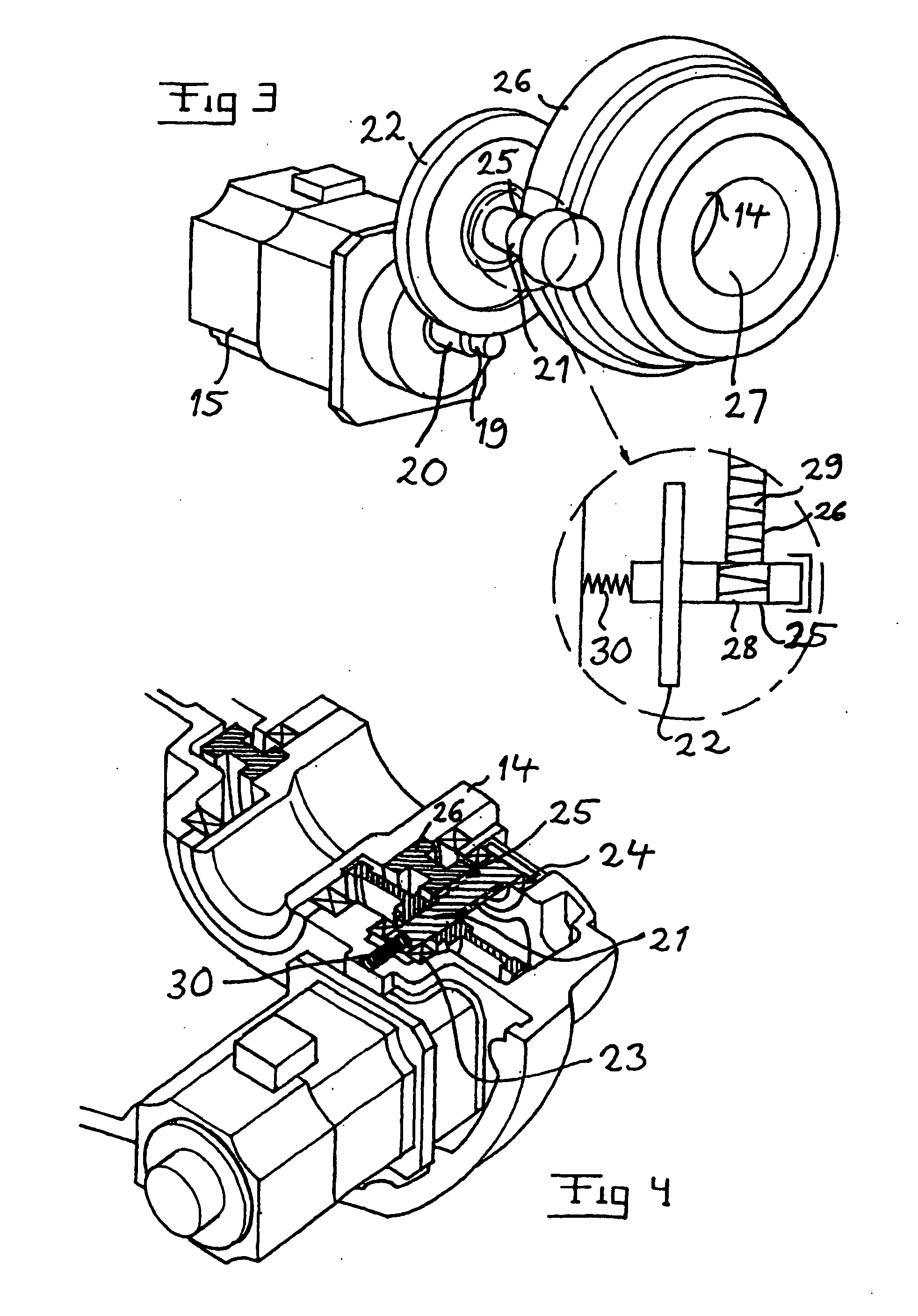
[0013]According to another embodiment of the invention, the robot exhibits means for eliminating any play in the last stage of the gear in that said
gear wheel, secured with respect to the third axis, and a penultimate
gear wheel meshing therewith exhibit wedge-like teeth in the direction of their axes of rotation, and that means are arranged for spring-loaded influence of said penultimate
gear wheel in the direction of said axes of rotation to mesh with said last gear wheel. In this way, it is ensured that the rotary motion of the upper arm relative to the lower arm may take place in a well-defined and even manner without any jumps, which is especially important if the robot is to carry out work that requires high precision. In addition, because of this wedge-like shape, the elimination of play with the
resultant rigidity between the robot arms in question will be maintained over time, since the teeth are worn into an increasingly better fit, and this together with the spring loading provides for a very small play.
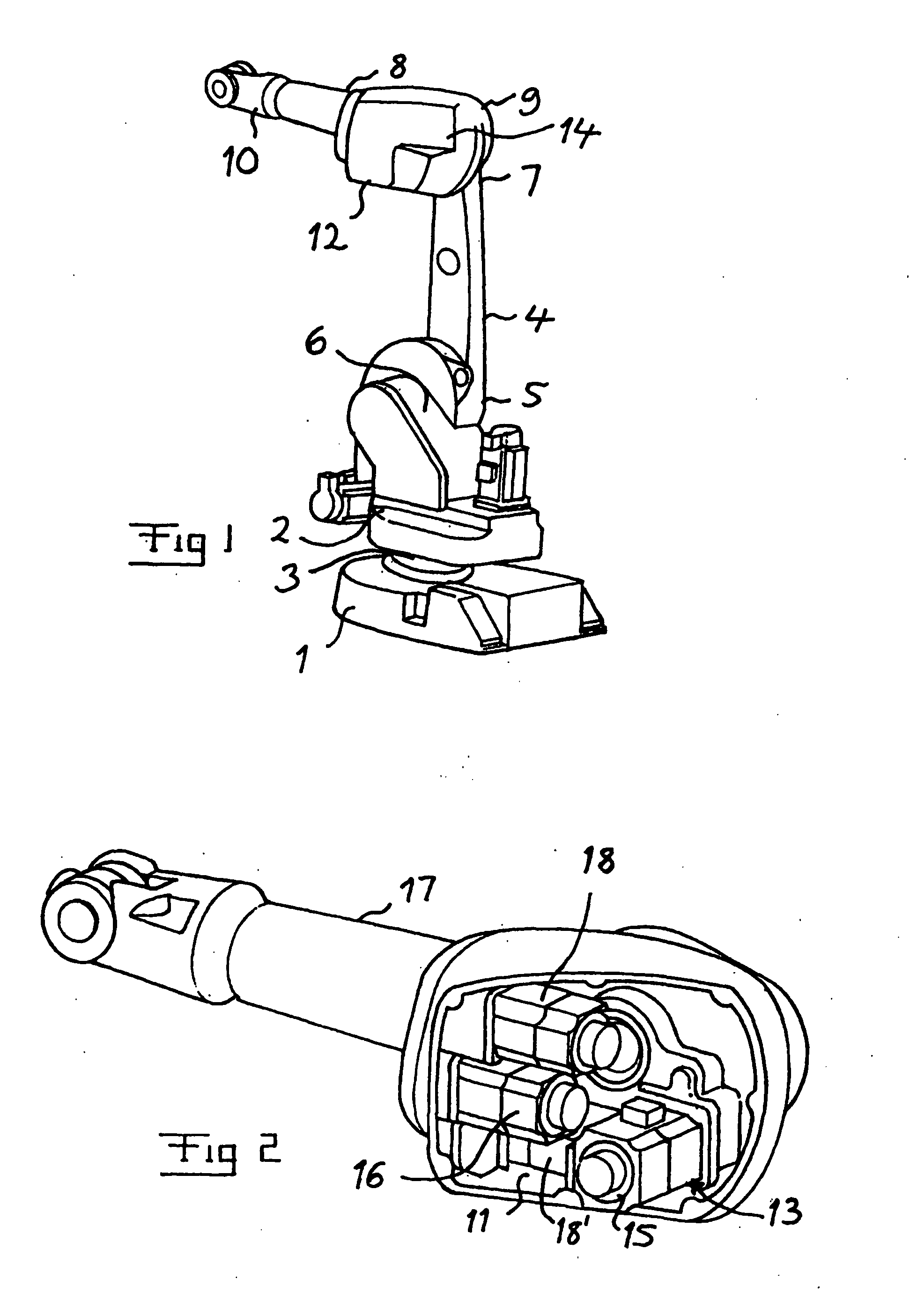
[0015]Thus, the drive package for the third axis is advantageously arranged in a said space that may be exposed by removing a housing, thus in a simple manner providing access to the parts of this drive package and any cables present there.
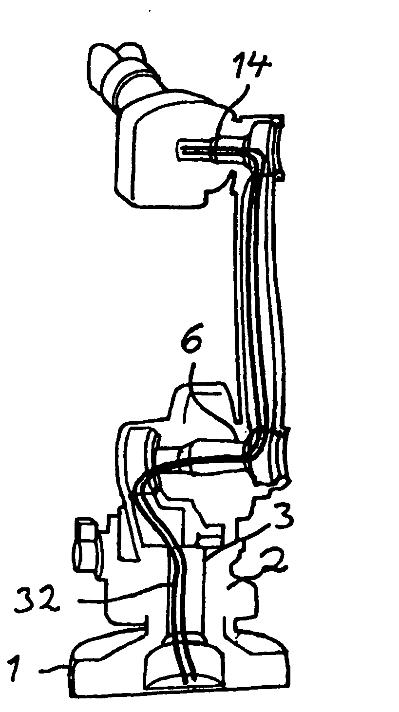
[0019]According to yet a further embodiment of the invention, the robot comprises so-called
client cables, extending from the interior of the base to the frame through said first axle, that is, cables which are specific for the intended use of the robot, such as
welding wires, and which do not belong to cables intended for controlling the movements of the robot. This is made possible because when using this type of gear, the axle in question may be simply made with a through-hole with a large cross section. It is especially advantageous to arrange a tube inside said first axle, said tube extending in the direction of said first axle and having a smaller outer
diameter than the inner
diameter of said axle, and to arrange the
client cables in the tube and the cables intended for controlling the movements of the robot in the space between the tube and the inner wall of the axle to tightly mutually insulate these two types of cable. When, for example, using
client cables for
welding purposes, relatively strong currents will flow therethrough, and without such a tight insulation they may disturb the task that is to be solved by the other cables of the robot.

