Valve-actuating system for an internal combustion engine, engine incorporating same, and method of using same

a valve-actuating system and internal combustion engine technology, applied in the direction of engines, machines/engines, mechanical apparatus, etc., can solve the problem of difficult to move the rocker arm smoothly to the desired position on the rocker arm shaft, and achieve smooth movement, without sacrificing the performance of the valve-actuating system, the effect of smooth movemen

Inactive Publication Date: 2008-10-30
HONDA MOTOR CO LTD
View PDF6 Cites 10 Cited by
  • Summary
  • Abstract
  • Description
  • Claims
  • Application Information

AI Technical Summary

Benefits of technology

[0018]According to the first aspect of the present invention, the outer peripheral surface of the rocker arm shaft, on the side to which the rocker arm is about to be moved, becomes virtually the same as the surface which has been just covered by the rocker arm per se. Such arrangement prevents a foreign object, which would otherwise interfere with the movement of the rocker arm, from being attached to the surface. Accordingly, the rocker arm can be smoothly moved. Moreover, even when such a foreign object enters between the rocker arm and the rocker arm shaft, the foreign object is discharged appropriately by a relative movement of the rocker arm and the rocker arm shaft. Accordingly the rocker arm can be maintained at favorable desirable position without sacrificing the performance of the valve-actuating system.
[0019]According to the second aspect of the present invention, along with the movement of the rocker arm shaft preceding that of the rocker arm, it is possible to remove a foreign object that may be present on the outer peripheral surface on the side to which the rocker arm is about to be moved, and simultaneously to accumulate a required force in one of the springs.
[0020]In addition, since the rocker arm is moved by a predetermined force accumulated in one of the springs, the movement of the rocker arm is less likely to be influenced by an oil temperature and the like in contrast to an arrangement utilizing an engine oil pressure for moving the rocker arm to a desired position. As a result, the rocker arm can be smoothly moved.
[0021]According to the third aspect of the present invention, the rocker arm is not moved before one of the springs accumulates the predetermined force. As a result, the rocker arm can be smoothly moved by utilizing the predetermined force accumulated in one of the springs.
[0022]According to the fourth aspect of the present invention, the predetermined force can be accumulated in one of the springs by moving the rocker arm shaft in the axial directions along with the spring-receiving portions. In other words, utilizing the rocker arm shaft as a part of the rocker-arm moving mechanism makes it possible to simplify the rocker-arm moving mechanism.

Problems solved by technology

Since such a foreign object may interfere with the movement of the rocker arm, it becomes difficult for the rocker arm to be smoothly moved to a desired position on the rocker arm shaft.

Method used


Image

  • Valve-actuating system for an internal combustion engine, engine incorporating same, and method of using same
  • Valve-actuating system for an internal combustion engine, engine incorporating same, and method of using same
  • Valve-actuating system for an internal combustion engine, engine incorporating same, and method of using same

Examples


Embodiment Construction

[0061]It should be understood that only structures considered necessary for illustrating selected embodiments of the present invention are described herein. Other conventional structures, and those of ancillary and auxiliary components of the system, will be known and understood by those skilled in the art.

[0062]Hereinafter, several illustrative embodiments of the present invention are described with reference to the accompanied drawings. In these drawings, for convenience of descriptions, the arrows FR, LH, and UP denote the frontward direction, the leftward direction, and the upward direction, respectively, in relation to a vehicle traveling direction.

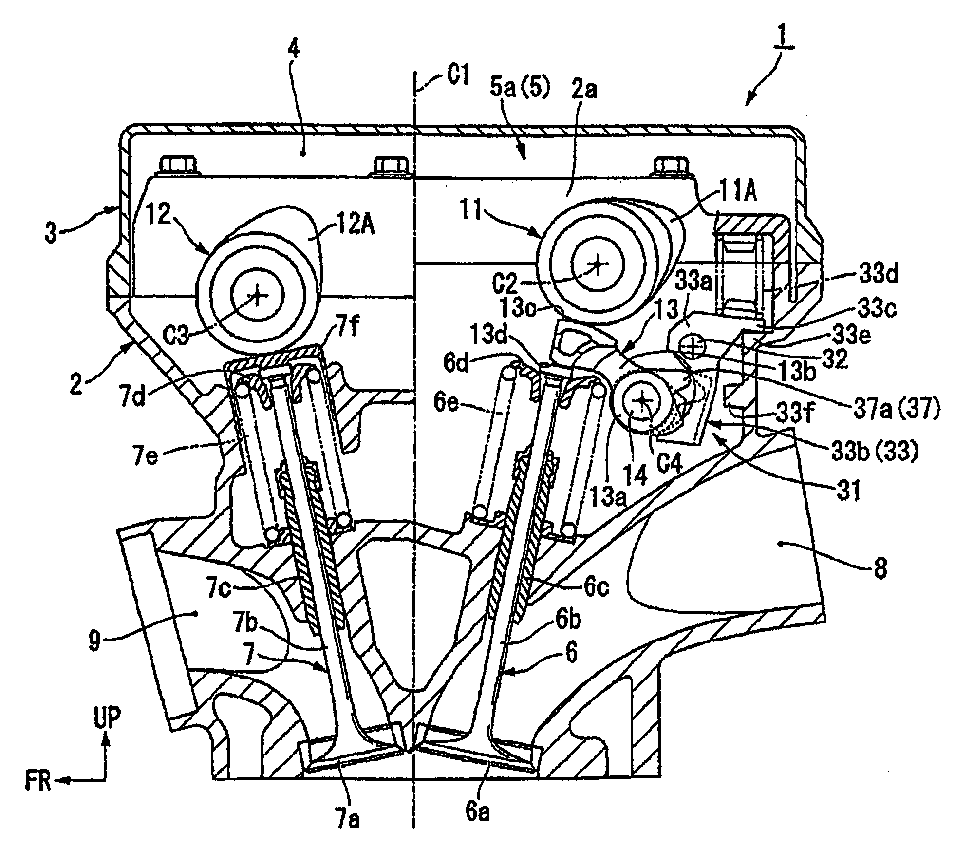
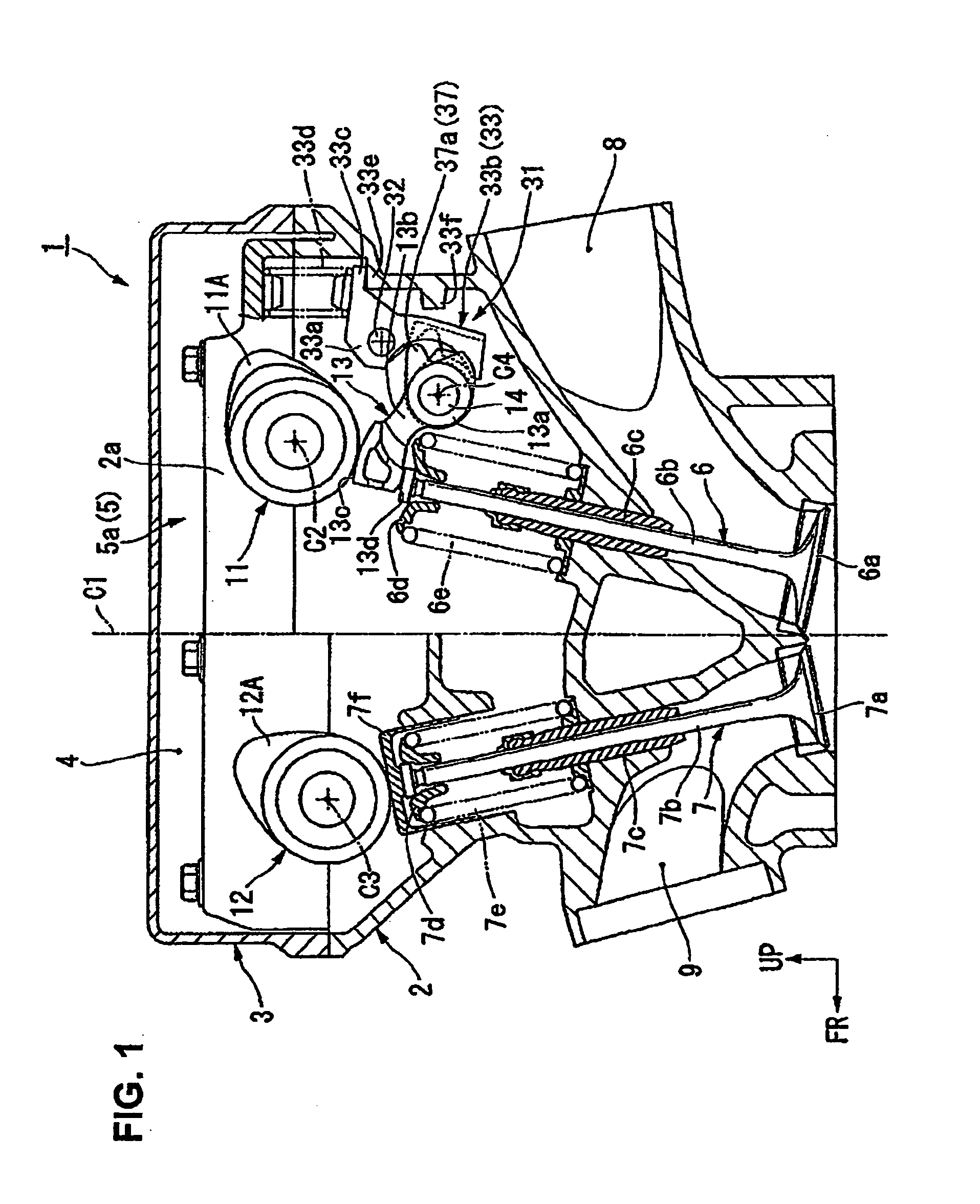
[0063]FIG. 1 is a left-side view showing a cylinder head 2 of a four-stroke, DOHC, parallel, four-cylinder engine 1. The engine 1 is used as a power source for a vehicle such as a motorcycle. The engine 1 includes a head cover 3 attached on top of the cylinder head 2. A valve-actuating system 5 is housed in a valve chamber 4 formed b...


PUM


Abstract

A valve-actuating system for an engine, in which left and right rocker arms are moved in axial directions of a rocker arm shaft to one of a first operating position in which the rocker arms are allowed to abut on first cams, and a second operating position in which the rocker arms are allowed to abut on second cams. The rocker arm shaft is slidably supported by an engine frame so as to be movable in the axial directions thereof. During an engine operation, when the left and right rocker arms are about to be selectively moved to one of the operating positions, the rocker arm shaft is moved in advance to the same side of the selected one of the operating positions, and thereafter the left and right rocker arms are moved to the selected one of the operating position.

Description

CROSS-REFERENCE TO RELATED APPLICATIONS[0001]The present application claims priority under 35 USC §119 based on Japanese patent application No. 2007-115493 filed on Apr. 25, 2007. The entire subject matter of this priority document is incorporated by reference herein.BACKGROUND OF THE INVENTION[0002]1. Field of the Invention[0003]The present invention relates to a variable valve-actuating system for a four-stroke engine of a vehicle such as a motorcycle, and to an engine incorporating same. More particularly, the present invention relates to a variable valve-actuating system including a camshaft having a pair of cams operatively associated with an engine valve, allowing one of the cams to be selectively used for opening and closing operations of the engine valve, and to a method of using same.[0004]2. Description of the Background Art[0005]There are number of known variable valve-actuating systems for internal combustion engines. Generally, such valve-actuating systems include a roc...

Claims


Application Information

Patent Timeline
Patent Type & Authority Applications(United States)
IPC IPC(8): F01L1/18
CPCF01L1/053F01L1/185Y10T74/2107F01L2001/0537F01L13/0036
Inventor YAMAMOTO, TOSHIOWARASHINA, TAKUYA
Owner HONDA MOTOR CO LTD
Why Eureka
Try Eureka