Method for operating an internal combustion engine

a technology of internal combustion engine and crankcase, which is applied in the direction of machines/engines, liquid fuel feeders, electric control, etc., can solve the problem of insufficient underpressure in the crankcase, and achieve the effect of stable easy determination and correction of times, and good internal combustion engine running behavior

Active Publication Date: 2008-10-30
ANDREAS STIHL AG & CO KG
View PDF5 Cites 9 Cited by
  • Summary
  • Abstract
  • Description
  • Claims
  • Application Information

AI Technical Summary

Benefits of technology

[0021]There is provision for the controller to define the opening time and the closing time as a function of the fuel quantity which is to be fed, and for the fuel quantity which is to be fed to be determined for each cycle of the internal combustion engine. Since the fuel quantity which is to be fed is determined precisely with respect to cycles, very good running behavior of the internal combustion engine is obtained. Rapid adaptation to changed conditions is possible so that the internal combustion engine reacts quickly.
[0022]The opening and closing times of the metering valve are advantageously determined as a function of the fuel quantity which is to be fed by means of a reference counterpressure, and at least one of the times, that is to say the opening time and/or the closing time, is corrected as a function of a parameter which takes into account the counterpressure at the outlet opening. Since the opening and closing times of the metering valve are first determined and subsequently corrected, both the determination and the correction of the times can take place comparatively easily and therefore very quickly. The correction advantageously takes place by means of a characteristic diagram here. However, it is also possible to provide for the correction to take place by means of a calculation. It is also possible to provide for the required fuel quantity and at least one parameter which takes into account the counterpressure at the outlet opening to be determined, and for the opening time an

Problems solved by technology

When the internal combustion engine starts there is also insufficient underp

Method used


Image

  • Method for operating an internal combustion engine
  • Method for operating an internal combustion engine
  • Method for operating an internal combustion engine

Examples


Embodiment Construction

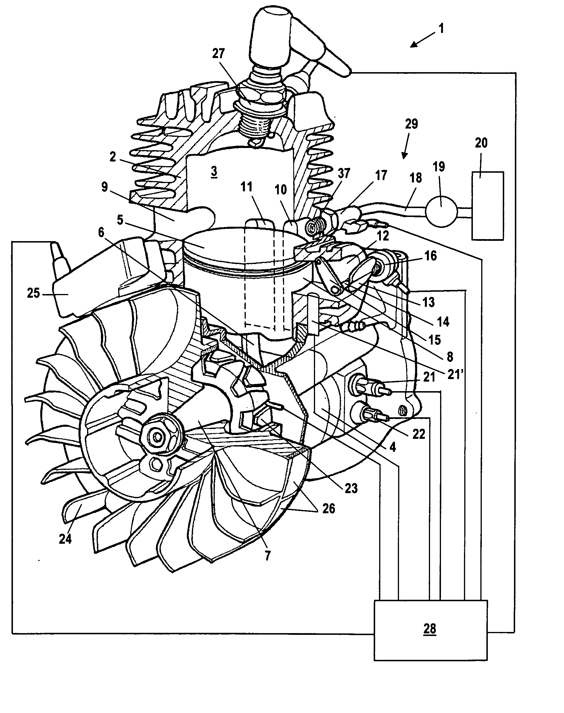
[0032]The internal combustion engine 1 which is shown in FIG. 1 is embodied as a single-cylinder two-stroke engine and is used to drive a tool in a hand-held implement such as a motor saw, a cut-off grinder, a clearing saw or the like. The method according to the invention can also be applied in other engines. The internal combustion engine 1 has a cylinder 2 in which a combustion chamber 3 is formed. The combustion chamber 3 is bounded by a piston 5. The piston 5 is mounted so as to move to and fro in the cylinder 2 and drives, by means of a connecting rod 6, a crankshaft 7 which is rotatably mounted in a crankcasing 4. An intake duct 12, which is slot-controlled by the piston 5, leads into the crankcasing 4. A throttle valve 13 with a throttle shaft 14 is pivotably mounted in the intake duct 12. In order to activate the throttle valve 13, a throttle lever 15, on which an accelerator cable (not shown in FIG. 1) can act, is arranged in a rotatably fixed fashion on the throttle shaft...


PUM


Abstract

A method for operating an internal combustion engine having a fuel system which feeds fuel at a given pressure to a metering valve provides that a controller defines the opening time and the closing time of the metering valve and correspondingly actuates the metering valve so that the metering valve opens and closes at the defined times. In order to permit precise metering of fuel even in high-speed internal combustion engines there is provision for the controller to define at least one of the times for the opening or closing of the metering valve while taking into account the counterpressure actually prevailing at the outlet opening of the metering valve.

Description

CROSS-REFERENCE TO RELATED PATENT APPLICATIONS[0001]The right of foreign priority is claimed under 35 U.S.C. §119(a) based on Federal Republic of Germany Application No. 10 2007 020 348.0, filed Apr. 30, 2007, the entire contents of which, including the specification, drawings, claims and abstract, are incorporated herein by reference.BACKGROUND OF THE INVENTION[0002]The invention relates to a method for operating an internal combustion engine.[0003]It is known to feed fuel to an internal combustion engine via a fuel system with a fuel pump and a metering valve.[0004]During operation, the pressure prevailing in the combustion chamber and crankcasing of the internal combustion engine fluctuates to a very high degree. The pressure fluctuates here both within a cycle as a function of the piston position and as a function of the rotational speed and the load. In metering valves which feed the fuel to the internal combustion engine at low overpressure, the fuel quantity which is fed to t...

Claims


Application Information

Patent Timeline
IPC IPC(8): F02M69/54
CPCF02B33/04F02B2075/125F02D41/345Y02T10/44Y02T10/123Y02T10/12Y02T10/40
Inventor ROSSKAMP, HEIKOMAIER, GEORGGEGG, TIMLAYHER, WOLFGANGKINNEN, ARNOHALLE, CHRISTINE
Owner ANDREAS STIHL AG & CO KG
Why Eureka
Try Eureka