Self-Cleaning Chlorine Generator with Intelligent Control

Inactive Publication Date: 2008-10-30
MAGEN ECO ENERGY A C S +1
View PDF4 Cites 15 Cited by
  • Summary
  • Abstract
  • Description
  • Claims
  • Application Information

AI Technical Summary

Benefits of technology

[0034]The pH-reducing agent is introduced into the electrolytic cell when the water inside the electrolytic cell is stagnant. The pH-reducing agent resident in the electrolytic cell, after having been used to clean mineral deposits from the electrolytic cells over an extended period of time, is flushed into the main body of water, thereby reducing the pH level in the main body of water, when water circulation through the electrolytic cell is re-activated.
[0035]Significantly, the volume of water within the electrolytic cell is small. Thus, only a small amount of pH-reducing agent is required to substantially lower the pH of the water in the electrolytic cell and to thereby cause removal of calcium depo

Problems solved by technology

If the pH is too high, it can adversely affect the water quality and the effectiveness of the chlorine generated by the generator.
The acid has a pH of about 0.1 and thus is extremely dangerous to handle and causes severe burns if it contacts the skin, open wounds, or the eyes.
Moreover, the electrolytic cells that generate the chlorine are subject to degradation due to the formation of mineral deposits, typically calcium, thereon.
Such manual cleaning is burdensome, risky, and has the disadvantage of using excessive amounts of acid.
Unfortunately, reversing polarity has detrimental effects on the electrolytic plates.
A PGM coating holds up well during anode operation, but steadily deteriorates during cathode operation.
Unfortunately, polarity reversal causes the plates to repeatedly charge up, and such charging up wears out the PGM coating at a much faster rate than steady state operation.
More specifically, charging the plates causes the plates to absorb a minor shock that wears out the PGM coating.
This method of reversing polarity is called the “soft start” method and reduces but does not eliminate wear on the plates.
However, even with routine reversal of polarity, the electro

Method used


Image

  • Self-Cleaning Chlorine Generator with Intelligent Control
  • Self-Cleaning Chlorine Generator with Intelligent Control
  • Self-Cleaning Chlorine Generator with Intelligent Control

Examples


Embodiment Construction

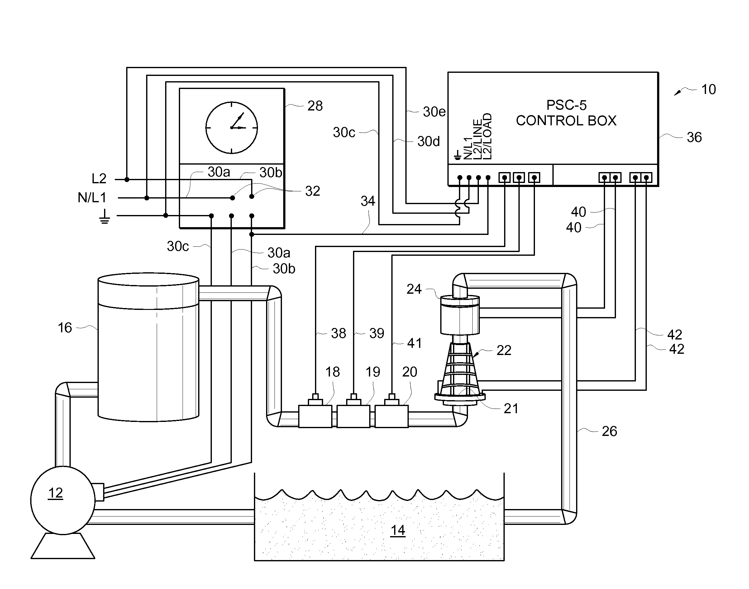
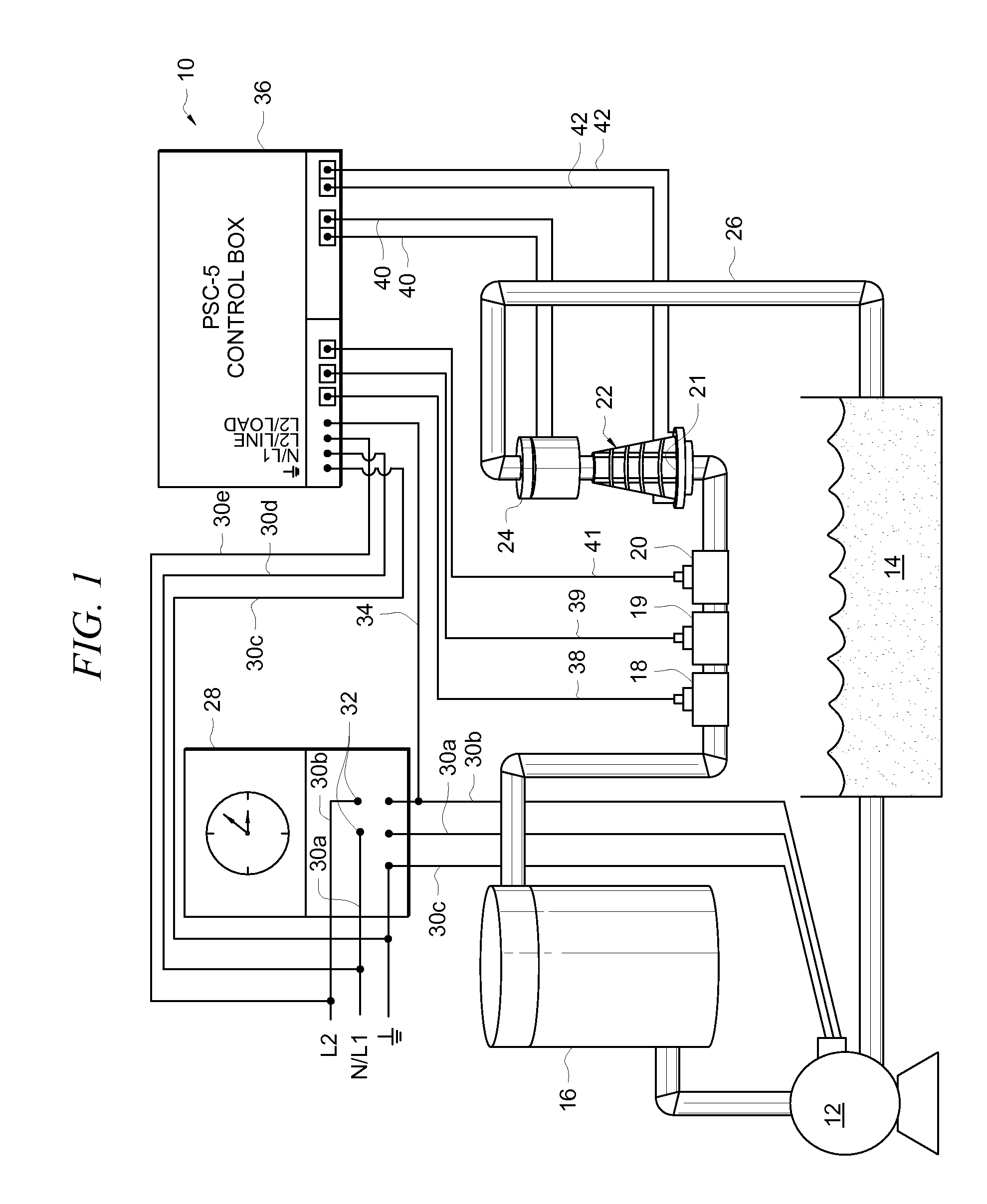
[0054]Referring now to the FIG. 1, it will there be seen that an illustrative embodiment of the invention is denoted as a whole by the reference numeral 10.

[0055]Circulation pump 12 draws water from swimming pool 14, or spa, fountain, well, or other main body of water, not shown, and pumps said water through filter 16, pH probe 18, ORP (oxidation reduction potential) probe 19, flow sensor 20, one-way check valve or other water-entrapment means 21 (such as a three-way valve with motor-operated actuators or a Hartford loop), electrolytic cell 22, also referred to herein as the cell, acid pump24, also referred to herein as an acid infusion means, and into pool 14 through return line 26.

[0056]The preferred water-entrapment means 21 in the embodiment of FIG. 1 is a Hartford loop, also known as an S-loop. If a one-way check valve is used, the pressure of the water is sufficient to open it.

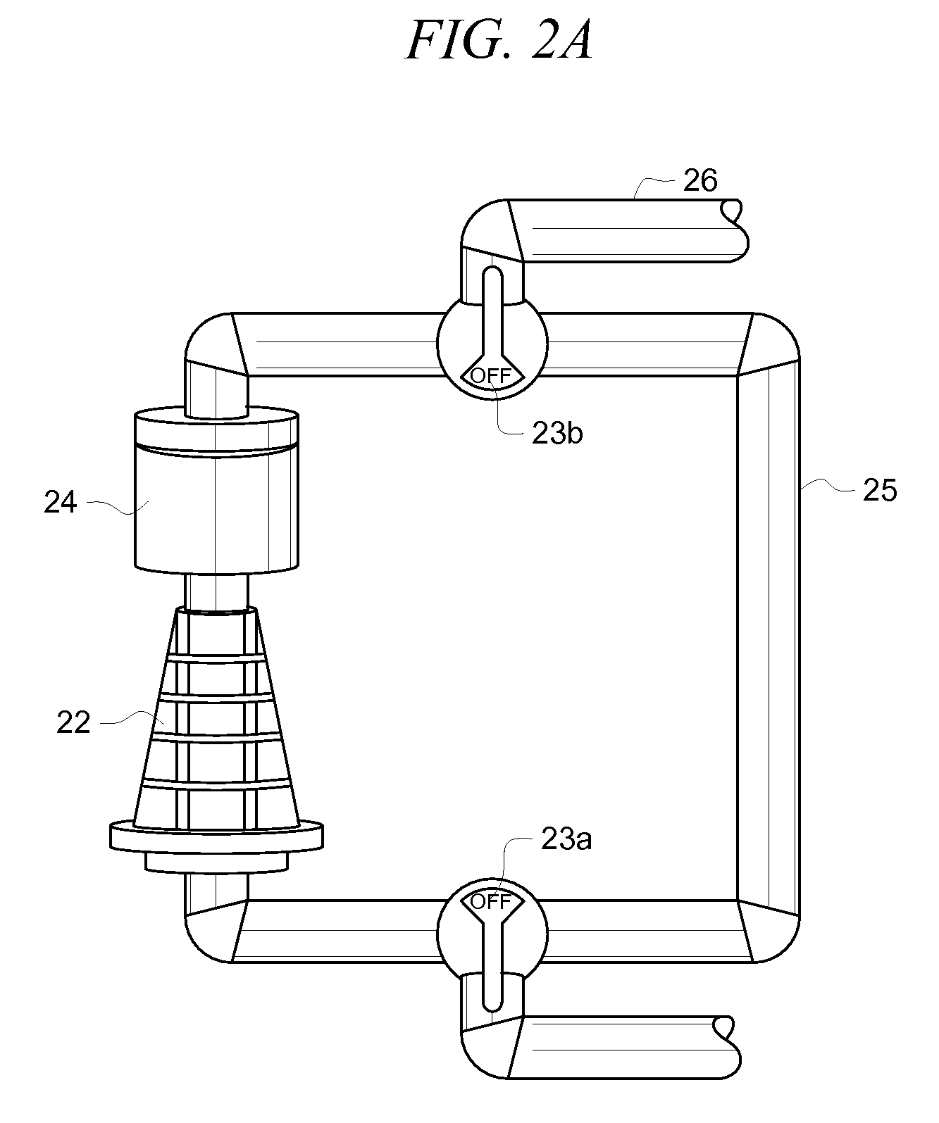
[0057]In installations lacking a cell isolation / bypass structure, such as the installation of FIG. 1,...


PUM

PropertyMeasurementUnit
Reduction potentialaaaaaaaaaa

Abstract

A water treatment system includes a circulation pump and a chlorine-generating electrolytic cell in fluid communication with a main body of water. When mineral deposits foul the generator, water is stagnated within the electrolytic cell and a minimal amount of a pH-reducing agent is added to remove the mineral deposits. The pH-reducing agent is admitted on a periodic timed basis or when the pH of the main body of water exceeds a predetermined threshold. Cleaning is accomplished by adding the pH-reducing agent when water in the electrolytic cell is not circulating so that the acid dwells within the electrolytic cell for a sufficient amount of time. Re-activation of circulation through the electrolytic cell causes the pH-reducing agent to enter the main body of water.

Description

CROSS-REFERENCE TO RELATED DISCLOSURES[0001]This disclosure is a continuation-in-part of U.S. patent application Ser. No. 10 / 711,419, entitled Self-Cleaning Chlorine Generator With pH Control, filed Sep. 17, 2004, by the present inventor. That disclosure is hereby incorporated by reference in its entirety into this disclosure.BACKGROUND OF THE INVENTION[0002]1. Field of the Invention[0003]This invention relates to electrolytic chlorine generators. More particularly, it relates to method for introducing a pH-reducing agent into an electrolytic cell for dissolving mineral deposits from electrolytic plates.[0004]2. Description of the Prior Art[0005]Electrolytic chlorine generators include electrolytic cells having plates that are coated on one side or both sides, depending upon the type of cell, with a platinum group metal (PGM) such as ruthenium, or similar coating.[0006]The operation of an electrolytic chlorine generator has the side effect of gradually increasing the pH level of a b...

Claims


Application Information

Patent Timeline
IPC IPC(8): B08B3/08C25B9/00
CPCC02F1/4674C02F2001/46119C02F2201/4615C02F2209/04C02F2209/06
Inventor EYAL, OMER C.
Owner MAGEN ECO ENERGY A C S
Why Eureka
Try Eureka