Self-cleaning chlorine generator with pH control

a chlorine generator and self-cleaning technology, applied in the field of electrolytic chlorine generators, can solve the problems of severe burns, adversely affecting the water quality and the effectiveness of the chlorine generated by the generator, and the electrolytic cells that generate the chlorine are subject to degradation, so as to reduce the ph level, reduce the ph of the water, and reduce the volume of water within the electrolytic chamber

Inactive Publication Date: 2009-03-24
MAGEN ECO ENERGY A C S +1
View PDF28 Cites 10 Cited by
  • Summary
  • Abstract
  • Description
  • Claims
  • Application Information

AI Technical Summary

Benefits of technology

[0035]In both embodiments, the pH-reducing agent is introduced into the electrolytic chamber when the circulating pump is not operating. The pH-reducing agent resident in the electrolytic chamber, after having been used to clean mineral deposits from the electrolytic cells over an extended period of time, is flushed into the main body of water, thereby reducing the pH level in the main body of water, when the water circulation pump is re-activated.
[0036]Significantly, the volume of water within the electrolytic chamber is small. Thus, only a small amount of pH-reducing agent is required to substantially lower the pH of the water in the electrolytic chamber and to thereby cause removal of calcium deposits. Thus, when the circulation pump is re-started, only a small amount of pH-reduced water is introduced into the swimming pool or other body of water under treatment. This prevents abrupt drops in the pH level of the body of water as a whole. Advantageously, the small injections of reduced pH water into the body of water serve to maintain the pH within the desirable range.
[0037]Accordingly, the electrolytic cells or plates are not removed from the electrolytic chamber prior to their cleaning by the muriatic acid. This advantageously saves the time expended in manually removing the electrolytic plates, cleaning them, and re-installing them. It also avoids wasteful use of the pH-reducing agent.

Problems solved by technology

If the pH is too high, it can adversely affect the water quality and the effectiveness of the chlorine generated by the generator.
The acid has a pH of about 0.1 and thus is extremely dangerous to handle and causes severe burns if it contacts the skin, open wounds, or the eyes.
Moreover, the electrolytic cells that generate the chlorine are subject to degradation due to the formation of mineral deposits, typically calcium, thereon.
Such manual cleaning is burdensome, risky, and has the disadvantage of using excessive amounts of acid.
Unfortunately, reversing polarity has detrimental effects on the electrolytic plates.
A PGM coating holds up well during anode operation, but steadily deteriorates during cathode operation.
Moreover, polarity reversal causes the plates to repeatedly charge up, and such charging up wears out the PGM coating at a much faster rate than steady state operation.
More specifically, charging the plates causes the plates to absorb a minor shock that wears out the PGM coating.
This method of reversing polarity is called the “soft start” method and reduces but does not eliminate the wear on the plates.
However, even with routine reversal of polarity, the electrolytic cells will still collect calcium deposits over time.
At least some of the calcium deposits will eventually flake off and foul the body of water.
In a swimming pool or spa, this unsightly debris is eventually suctioned by a pool cleaner or pool drain into a pool filter where the calcium is collected.
The calcium content of the water thus drops over time and requires replenishment because a swimming pool having low-calcium water will aggressively attack various pool walls and equipment.
This high salinity adversely affects some swimmers if the main body of water is a swimming pool.
Such high salinity may disqualify an electrolytic chlorinator from use where the main body of water is a fountain because salt may leave white marks on fixtures after a fixture has been splashed and the splashed water has evaporated.
Unfortunately, plates that are spaced close to one another become fouled with mineral deposits at a substantially faster rate than more widely spaced plates.
Since maintaining higher flow rates often requires increased energy and equipment expenditures and the increased use of polarity reversal wastes the PGM, most systems forego the closer plate spacing and continue to require high salinity.
However, such pumps are expensive and are subject to wearing out.
This method has the drawback of causing aggressive chemicals such as hydrochloric acid to attack the circulating pump, filters, heaters, and any other equipment that might be present in the system.

Method used


Image

  • Self-cleaning chlorine generator with pH control
  • Self-cleaning chlorine generator with pH control
  • Self-cleaning chlorine generator with pH control

Examples


Embodiment Construction

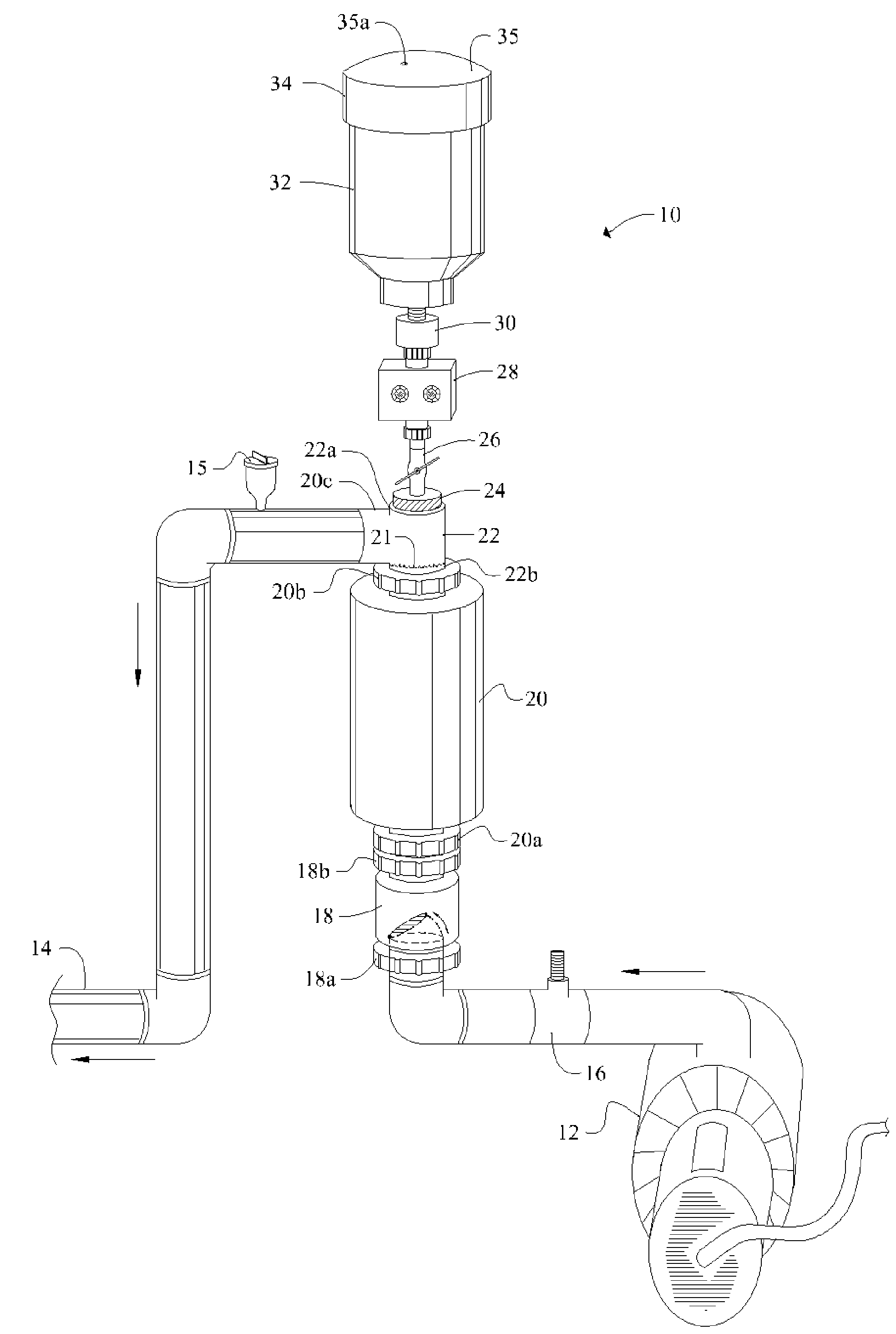
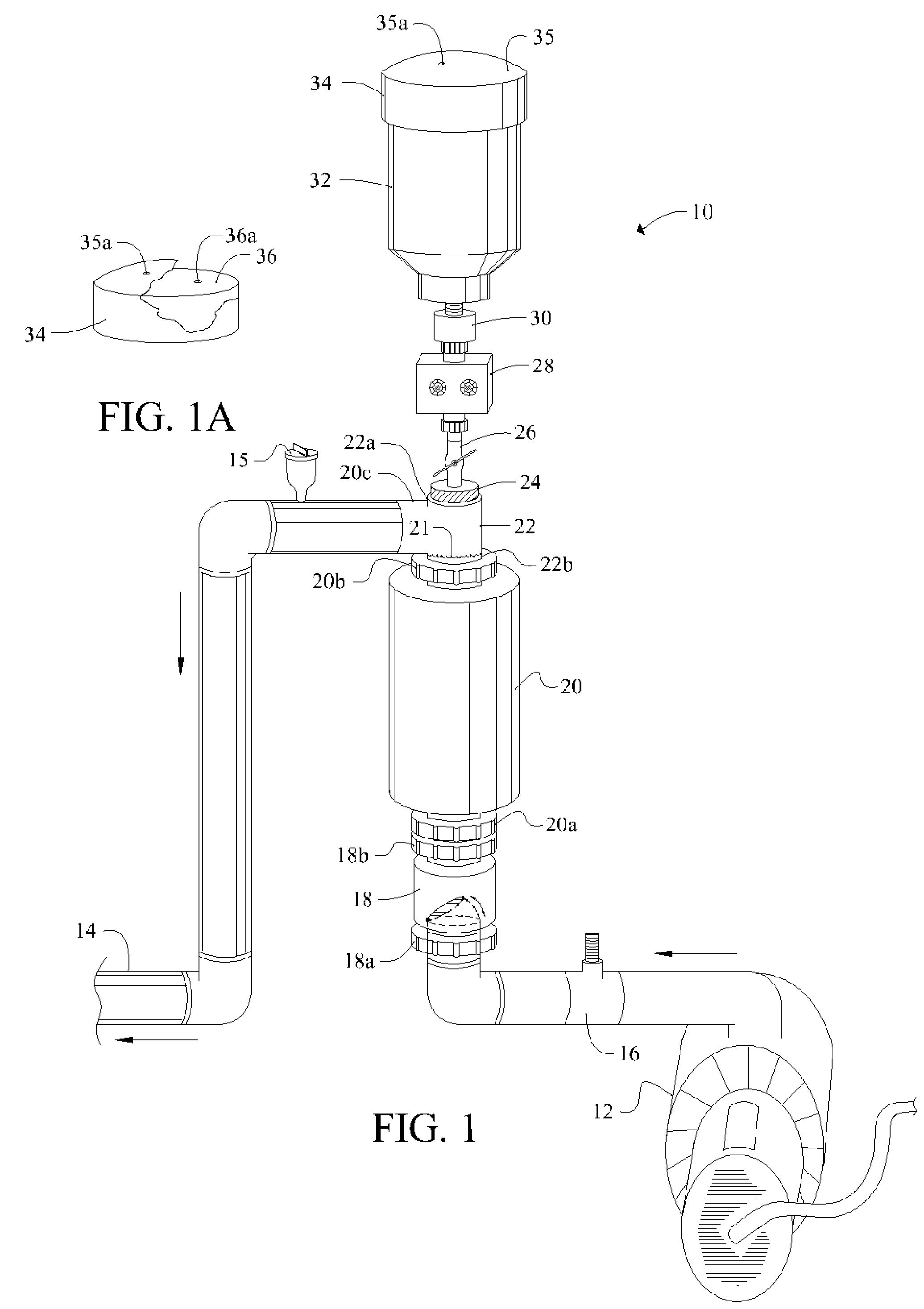
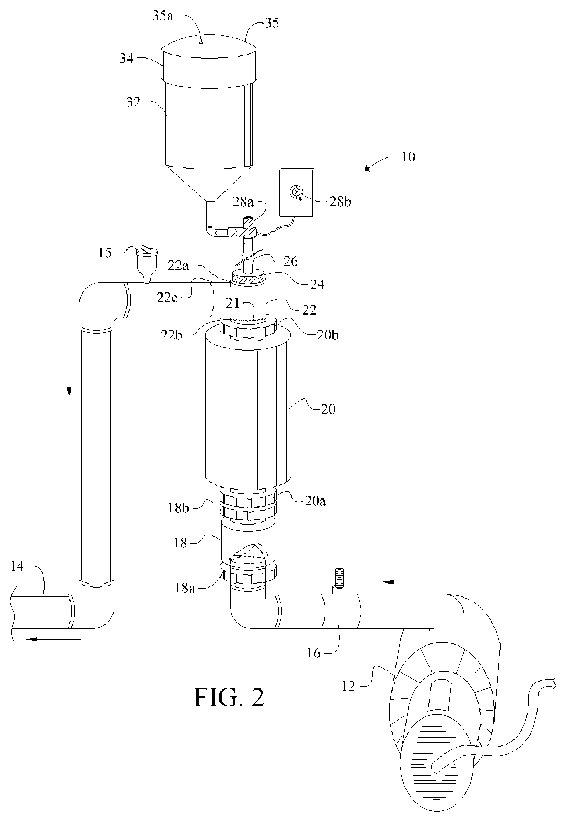
[0048]Referring now to FIG. 1, it will there be seen that an illustrative embodiment of the invention is denoted as a whole by the reference numeral 10.

[0049]Novel chlorine generator and plate-cleaning assembly 10 is positioned in line between a circulation pump 12 and return line 14.

[0050]Circulation pump 12 draws water from a swimming pool, spa, fountain, well, or other main body of water, not shown, and pumps said water through flow switch 16, one-way check valve 18, electrolytic chamber 20, T-shaped conduit 22, and outlet 14. Electrolytic chamber 20 is vertically oriented.

[0051]Cap 24 screw-threadedly engages uppermost branch 22a of T-shaped conduit 22 and is adapted to screw-threadedly receive ball valve 26. Infusion means 28 surmounts said ball valve 26. Container or reservoir 32 surmounts said infusion means 28. Removable cap 34 provides a closure means for container 32.

[0052]Positioning reservoir 32 above electrolytic chamber 20 as depicted enables a pH-reducing agent in sai...


PUM

PropertyMeasurementUnit
pHaaaaaaaaaa
timeaaaaaaaaaa
period of timeaaaaaaaaaa

Abstract

A water treatment system includes a circulation pump and an electrolytic chamber in fluid communication with a main body of water. Electrolytic plates within the electrolytic chamber generate chlorine. When mineral deposits foul the electrolytic plates, water is isolated within the electrolytic chamber and a minimal amount of a pH-reducing agent is added to the electrolytic chamber to remove the mineral deposits. In a first embodiment, the pH-reducing agent is admitted on a periodic timed basis. In a second embodiment, the pH-reducing agent is added when the pH of the main body of water falls below a predetermined threshold. In both embodiments, cleaning is accomplished by adding the pH-reducing agent when the circulation pump is not operating so that the acid dwells within the electrolytic chamber for a sufficient amount of time. Activation of the circulation pump causes the pH-reducing agent to enter the main body of water.

Description

BACKGROUND OF THE INVENTION[0001]1. Field of the Invention[0002]This invention relates to electrolytic chlorine generators. More particularly, it relates to means for introducing a pH-reducing agent into an electrolytic chamber for dissolving mineral deposits from electrolytic cells.[0003]2. Description of the Prior Art[0004]Electrolytic chlorine generators include electrolytic cells having plates that are coated on one side or both sides, depending upon the type of cell, with a platinum group metal (PGM) such as ruthenium, or similar coating.[0005]The operation of an electrolytic chlorine generator has the side effect of gradually increasing the pH level of a body of water undergoing such chlorination. If the pH is too high, it can adversely affect the water quality and the effectiveness of the chlorine generated by the generator. Accordingly, the pH level of a swimming pool, spa, fountain, well, or other body of water equipped with an electrolytic chlorine generator and a circulat...

Claims


Application Information

Patent Timeline
Patent Type & Authority Patents(United States)
IPC IPC(8): C25C1/02C02F1/461C25B15/00
CPCC02F1/46109C02F1/66C25B15/00C02F1/4674C02F2001/46119C02F2103/42C02F2209/44C02F2303/16
Inventor EYAL, OMER C.
Owner MAGEN ECO ENERGY A C S
Why Eureka
Try Eureka