
Optical distortion removal

a technology of optical distortion and removal, applied in the field of optical distortion removal, can solve the problems of affecting the optical properties of the glass, the manufacture of glass, and the influence of the surface irregularities and ultimately optical properties, so as to reduce optical distortion, eliminate the need for polishing, and increase the strength of the article

Inactive Publication Date: 2008-10-30
CORNING INC
View PDF8 Cites 28 Cited by
  • Summary
  • Abstract
  • Description
  • Claims
  • Application Information

AI Technical Summary

Benefits of technology

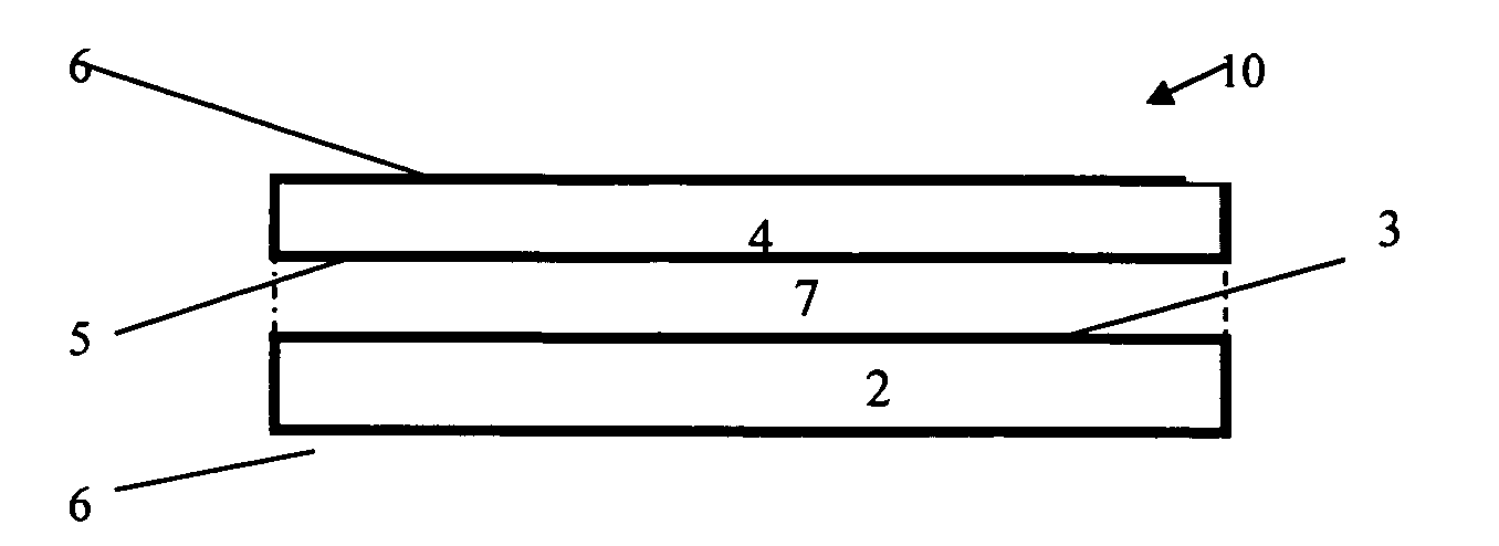
[0012]The present invention describes an article and method that reduces optical distortion in transparent materials, where the optical distortion is caused by surface irregularities. The method can eliminate the need for polishing, can increase the strength of the article, and is both inexpensive and rapid.
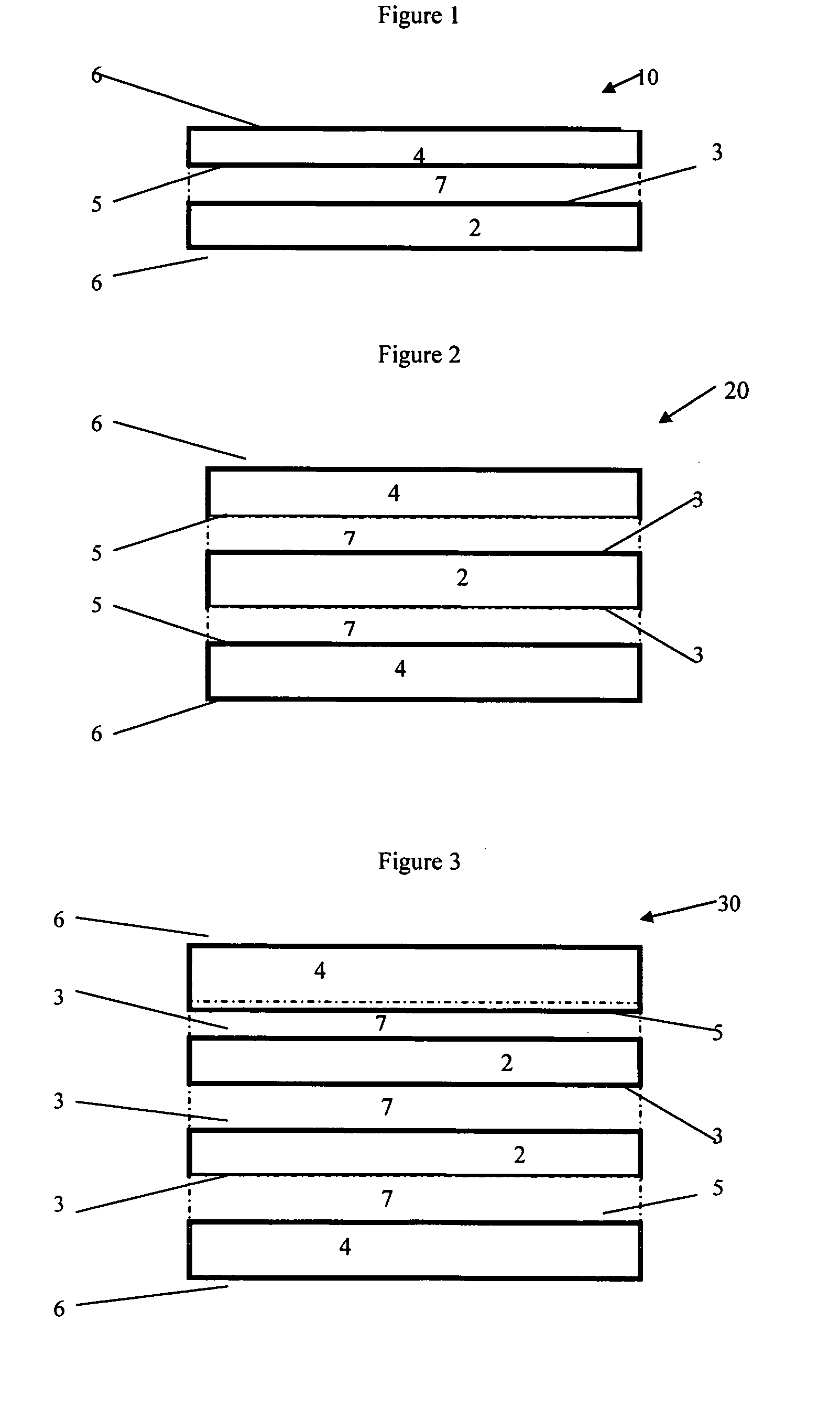
[0015]In one embodiment, the article includes a first object comprising a rolled glass product. Such products may have thicknesses of more than 7 cm. The rolled glass product includes two optically distorting surfaces. The second object consists essentially of two float glass sheets having a thickness of less than 1 mm. A PVB adhesive secures one float glass sheet to each optically distorting surface. The article is essentially free of a visible optical distortion. Polishing of the rolled glass product is eliminated.
[0016]In another embodiment, the article includes a plurality of first objects having optically distorting surfaces and at least two second objects having a substantially distortion-free surface. The second objects sandwich the first objects so that the distortion-free surface defines the outer surfaces. An index-matched adhesive bonds the objects. The resultant article essentially free of a visible optical distortion, and polishing is avoided.

Problems solved by technology

Although transparent, surface irregularities in the glass may result in optical distortions.
Irregularities may be formed, for example, during manufacture, in use or service, or as a result of damage.
The method of manufacture of the glass significantly affects surface irregularities and ultimately optical properties.
Unfortunately, not all glasses are amenable to the float process.
Viscosities, chemical compositions, and thicknesses of the glass are all limiting factors.
The fusion process can accommodate thicker glasses; however, the cost increases substantially and only higher viscosity glass compositions are suitable for fusion.
Irregularities include roughness and waviness, and manifest as optical distortions.
Roughness often produces haziness associated with diffuse reflection from the surface.
Waviness, that is, the distance between peaks and valleys on the surface of the rolled glass, results in gross optical distortions.
Such large surface irregularities produce significant optical distortion.
Unfortunately, thicker glass requires higher roll pressure so larger irregularities appear on the glass surface.
Of course, thicker glasses having low optical distortion may be produced using the cast or fusion processes, but the cost of glasses produced in this manner is often not commercially viable.
Grinding and polishing, hereinafter polishing, of rolled glasses adds to the time and cost of producing a glass that is free of optical distortion.
The roll process is often used to produce thick, hard glasses that cannot easily be manufactured by any other method.
Harder glasses are more difficult to polish.
Thicker glass results in larger irregularities to be polished.
Both factors increase polishing costs.
Additionally, polishing often removes material from the glass and can thereby reduce the glass' mechanical integrity.
The glass itself retains its original breaking properties but, if the laminated glass is cracked or broken, the flexible material may hold the glass fragments in place.
The crack or chip impairs the transparency of the glass and can create an optical distortion.
Care must be taken to level the resin with the surface of the glass; otherwise, optical distortion, such as lensing, may occur.

Method used


Image

  • Optical distortion removal
  • Optical distortion removal

Examples


example 2

[0034]Transparent armor for use as windows in armored vehicles may comprise multiple layers of float glass laminated together by an autoclave process. Each layer of float glass has a distortion-free surface. The transparent armor comprises a laminate of multiple layers of float glass. The armor may be more than four inches thick and weigh more than 50 pounds per square foot. Glass-ceramic windows with similar armor properties are typically more than thirty percent lighter. Float or fusion processes do not lend themselves to producing a thick, glass-ceramic sheet, so a transparent glass-ceramic sheet is produced by the rolled glass process. Prior art glass-ceramic windows required expensive, time-consuming polishing that ground away material and weakened the glass-ceramic.

[0035]A glass-ceramic sheet was produced by the rolled glass process. The rollers were polished to a nominally smooth finish, but the resulting glass-ceramic sheet had visibly textured surfaces and unacceptable opti...


PUM

PropertyMeasurementUnit
roughnessaaaaaaaaaa
thicknessaaaaaaaaaa
thicknessesaaaaaaaaaa

Abstract

The present invention describes an article that is substantially free of optical distortion and a method for eliminating or substantially reducing the need for conventional polishing of transparent objects. The article comprises a laminate of an optically distorting transparent object bonded with an adhesive to at least one transparent object that has a distortion-free surface. The indices of refraction of the adhesive and the objects are preferably within 0.2. The method includes adhesively bonding an optically distorting transparent object to one or more transparent objects having distortion-free surfaces so that the distortion-free surface is exposed.

Description

FIELD OF THE INVENTION[0001]The invention relates to an article and method for removing optical distortions caused by surface imperfections in transparent materials, particularly specialty glass sheets.BACKGROUND OF THE INVENTION[0002]Glass has many useful properties, of which optical transparency is one of the more important. Although transparent, surface irregularities in the glass may result in optical distortions. Irregularities may be formed, for example, during manufacture, in use or service, or as a result of damage. Surface irregularities include surface roughness, waviness or ripples, cut or saw marks, point defects, scratches, etc. The method of manufacture of the glass significantly affects surface irregularities and ultimately optical properties.[0003]Glass, glass-ceramics, and ceramics, hereinafter collectively glass, may be formed by batch processes, such as blown, pressed and cast, or continuous processes, such as rolled, fusion and float. Manufactures tend to favor c...

Claims


Application Information

Patent Timeline
Patent Type & Authority Applications(United States)
IPC IPC(8): B32B27/36B32B17/06B32B27/30
CPCB32B17/10036B32B17/10761Y10T428/24777Y10T428/26Y10T428/24355F41H5/0407Y10T428/31786Y10T428/31855Y10T428/31935Y10T428/31507B32B17/10733B32B17/1077
Inventor ZHANG, JIAN-ZHI JAY
Owner CORNING INC
Learn More