Consumable Electrode Type Arc Welding Machine

a consumable electrode and arc welding technology, applied in the direction of dc-dc conversion, electrode supporting devices, manufacturing tools, etc., can solve the problems of uncontrollable state in arc period, current control in short-circuit period, and uncontrollable state in conventional welding control method, etc., to prevent the occurrence of such uncertainty factors

Inactive Publication Date: 2008-10-30
PANASONIC CORP
View PDF5 Cites 42 Cited by
  • Summary
  • Abstract
  • Description
  • Claims
  • Application Information

AI Technical Summary

Benefits of technology

[0007]A consumable electrode type arc welding machine of the present invention supplies wire for generating an arc between the wire and base metal of welding. The welding machine includes a welding voltage detection circuit for detecting a welding voltage and outputting a welding voltage detection signal, a welding current detection circuit for detecting a welding current and outputting a welding current detection signal, a short-circuit arc judgment circuit for judging whether it is in a short-circuit state or in an arc state and outputting a short-circuit arc judgment signal after accepting the welding voltage detection signal, a short-circuit waveform control circuit for outputting a short-circuit waveform control signal after accepting the welding current detection signal, an arc waveform control circuit for outputting an arc waveform control signal for arc period after accepting the welding voltage detection signal, and a switching circuit for selectively outputting the arc waveform control signal in an arc period or the short-circuit waveform control signal in a short-circuit period in accordance with the short-circuit arc judgment signal after accepting the short-circuit waveform control signal and the arc waveform control signal. The welding power is controlled by an output from the switching circuit. The welding machine further includes an arc resistance calculator for calculating and outputting an arc resistance signal after accepting the welding voltage detection signal and the welding current detection signal. The arc resistance signal is inputted to at least either one of the short-circuit waveform control circuit and the arc waveform control circuit, for controlling the welding power.
[0008]Another consumable electrode type arc welding machine in the present invention supplies wire for generating an arc between the wire and base metal of welding. The welding machine includes a welding voltage detection circuit for detecting the welding voltage and outputting a welding voltage detection signal, a welding current detection circuit for detecting a welding current and outputting a welding current detection signal, a short-circuit arc judgment circuit for judging whether it is in a

Problems solved by technology

In such a conventional method of welding control, however, a state that is uncontrollable by means of the voltage control in arc period, or the current control in short-circuit period, would occur; such a state can be caused for example by the emergence of a micro s

Method used


Image

  • Consumable Electrode Type Arc Welding Machine
  • Consumable Electrode Type Arc Welding Machine
  • Consumable Electrode Type Arc Welding Machine

Examples


first exemplary embodiment

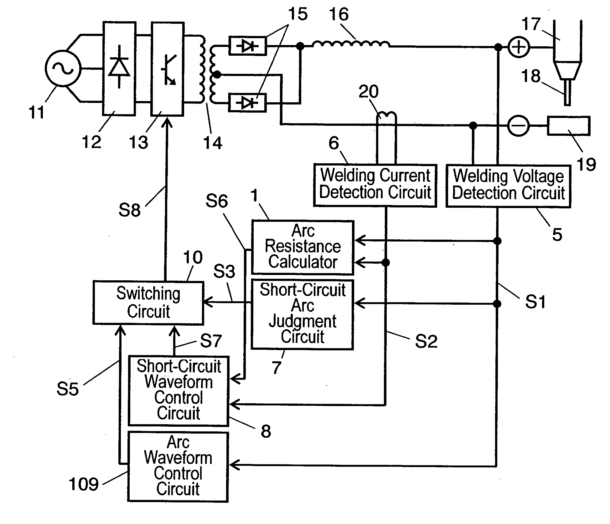
[0048]A consumable electrode type arc welding machine in accordance with a first exemplary embodiment of the present invention is described referring to FIGS. 1 and 2. Those constituent portions identical to those of the conventional consumable electrode type arc welding machine described in the above referring to FIG. 5 are designated by using the same symbols, and detailed description of these portions are eliminated. The main point of difference of the arc welding machine in the first embodiment as compared with the conventional counterpart is in short-circuit waveform control circuit 8, and that arc resistance calculator 1, which will be described later, is added.

[0049]In FIG. 1, welding voltage detection circuit 5 detects the welding voltage, and outputs welding voltage detection signal S1. Welding current detection circuit 6 detects the welding current, and outputs welding current detection signal S2. Arc resistance calculator 1 treats welding voltage detection signal S1 and w...

second exemplary embodiment

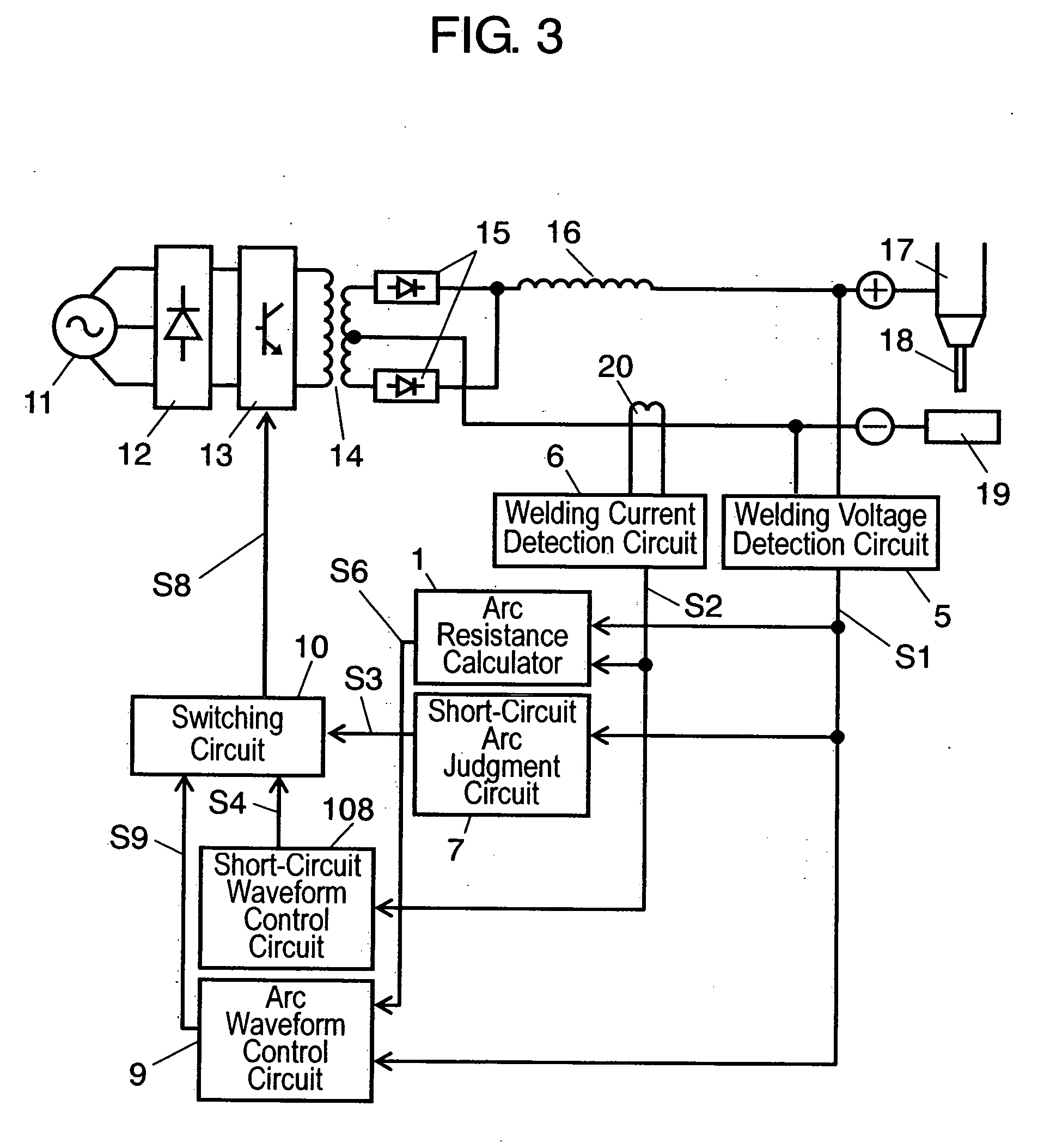
[0052]FIG. 3 is a block diagram showing the outline structure of a consumable electrode type arc welding machine in accordance with a second exemplary embodiment of the present invention. In FIG. 3, those portions having identical structure as those in the first embodiment are identified by designating with the same marks, and their detailed descriptions are eliminated. The point of difference as compared with the first embodiment is in short-circuit waveform control circuit 108 and arc waveform control circuit 9, and that the output of arc resistance calculator 1 is delivered to arc waveform control circuit 9, instead of short-circuit waveform control circuit 108.

[0053]In FIG. 3, arc resistance calculator 1 accepts welding voltage detection signal S1 from welding voltage detection circuit 5 and welding current detection signal S2 from welding current detection circuit 6 as input signals. Arc resistance calculator 1 calculates an arc resistance value from these input signals, and de...

third exemplary embodiment

[0058]Those constituent portions of the present embodiment having identical structure as those in the first and the second embodiments are designated with the same marks, and the detailed description of such portions are eliminated. The main point of difference from the first and the second embodiments is that the present embodiment is further provided with constant-current control circuit 2, constant-current control period setting unit 3 and second switching circuit 4; aiming to prevent an arc break by introducing a constant-current control when the welding current dropped in an arc period. Description on these portions will come later.

[0059]In FIG. 4, arc resistance calculator 1 calculates arc resistance value from welding voltage detection signal S1 and welding current detection signal S2, and outputs the result of calculation result as arc resistance signal S6, to constant-current control period setting unit 3, short-circuit waveform control circuit 8 and arc waveform control ci...


PUM

PropertyMeasurementUnit
Electrical resistanceaaaaaaaaaa
Arc resistanceaaaaaaaaaa

Abstract

A consumable electrode arc-welding machine comprising an arc resistance calculating part that calculates an arc resistance from a welding current and a welding voltage to develop an arc resistance signal, wherein the welding current and welding voltage are controlled by a short-circuit waveform control signal and an arc waveform control signal that vary in accordance with the arc resistance signal. In this way, the spatter control and the arc stability can be achieved. During an arc period, if the arc resistance signal exhibits a level greater than a predetermined level for a predetermined period, a constant current control signal is developed to perform a constant current control of the welding current by use of a predetermined current value that is higher than the current value developed during the development of the arc waveform control signal, thereby preventing the arc from going off.

Description

[0001]This application is a U.S. National Phase application of PCT International Application PCT / JP2006 / 304946 filed Mar. 14, 2006.TECHNICAL FIELD[0002]The present invention relates to a consumable electrode type welding machine which makes an arc discharge between a welding wire (hereinafter referred to as wire) and a base metal of welding (base metal) for welding.BACKGROUND ART[0003]It has been generally known that the conventional consumable electrode type welding machine, which makes use of an arc between wire and base metal, controls the voltage during arc period while it controls the current during short-circuit period. This type of technology has been disclosed in, for example, Japanese Patent Unexamined Publication No. H10-109163.[0004]FIG. 5 shows a schematic diagram of the conventional consumable electrode type arc welding machine. In the conventional consumable electrode type arc welding machine shown in FIG. 5, output of incoming power of three-phase AC 11 is rectified b...

Claims


Application Information

Patent Timeline
IPC IPC(8): B23K9/10
CPCB23K9/0734B23K9/092H02M3/33507H02M2001/0009H02M1/0009
Inventor NAGANO, MOTOYASUSHIMABAYASHI, SHINSUKE
Owner PANASONIC CORP
Why Eureka
Try Eureka