Ultrasonic nozzle

Inactive Publication Date: 2008-10-30
KELLOGG NORTH AMERICA
View PDF43 Cites 24 Cited by
  • Summary
  • Abstract
  • Description
  • Claims
  • Application Information

AI Technical Summary

Benefits of technology

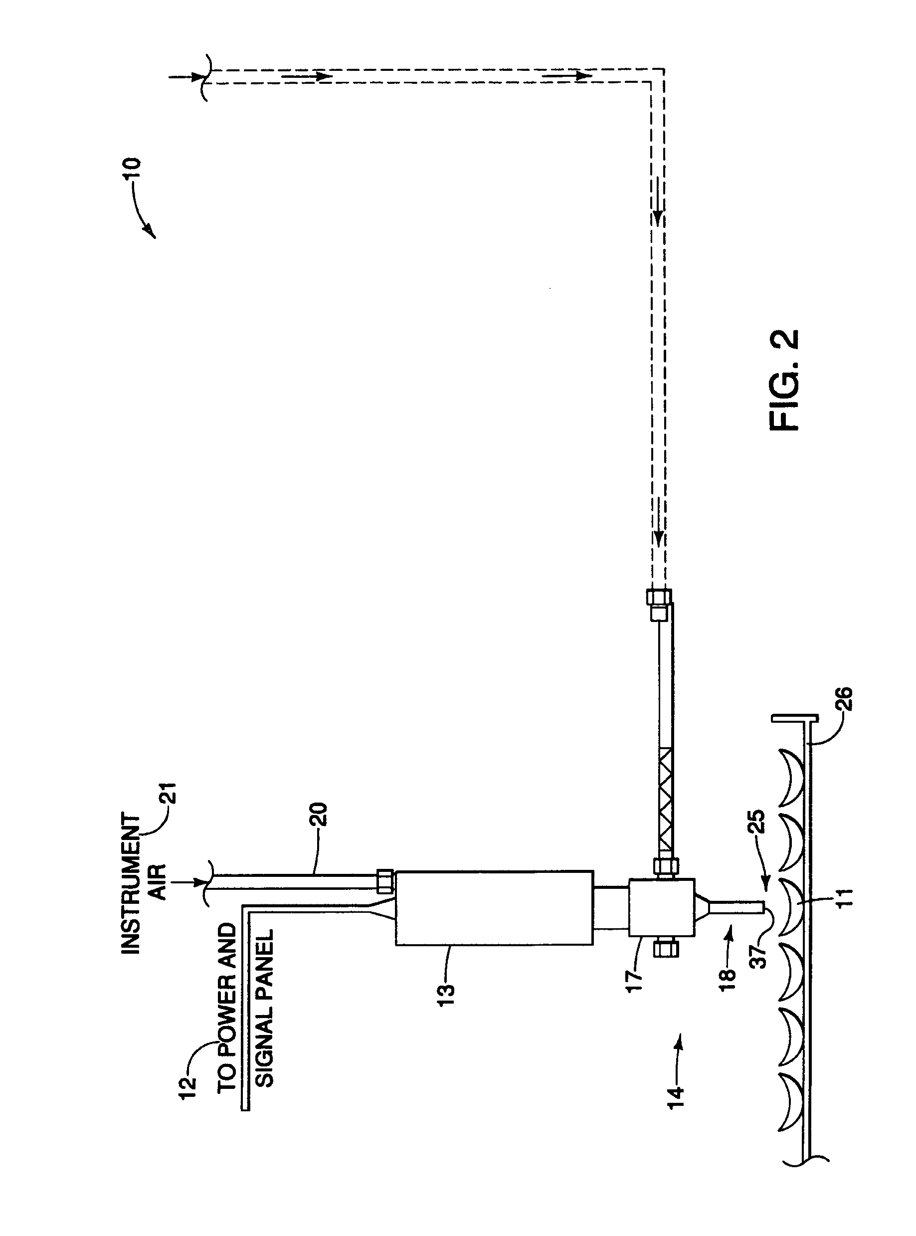
[0121]Referring to FIG. 2, in an alternative embodiment, the ultrasonic apparatus 10 may optionally include an air instrument 20. An air supply 21 provides a source of compressed air which flows to an air instrument 20. The air instrument 20 can be in the form of a tube (not shown) which can extend into a tumbler drum 23 (FIG. 3) or the converter 13. The air instrument 20 can have a plurality of air outlets, each of whic

Problems solved by technology

One disadvantage involves the difficulty of applying low flow rates, especially below 500 ml/min.
The conventional hydrostatic pressurized nozzle is known to have difficulty maintaining a good spray pattern at an accurate flow rate.
These low flow rates are often required for fluid additives to the food substrate, especially when applying expensive or highly functional materials.
Another disadvantage involves the difficulty of spraying slurry of large particle sizes.
Nozzle clogging is known to be one of the major drawbacks of slurry applications.
Yet another disadvantage involves the gradual build-up of the slurry upon the interior of the nozzle.
Thus, slurry build-up requires the direct cost of maintenance servicing.
More importantly, since most processing lines are generally continuous, slurry build-up can cause more significant cost of downtime of the entire processing line.
Still another problem resides in the momentum of spray from the

Method used

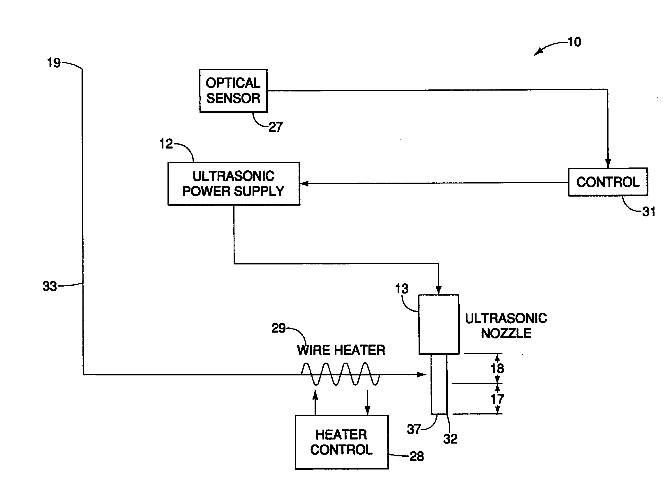
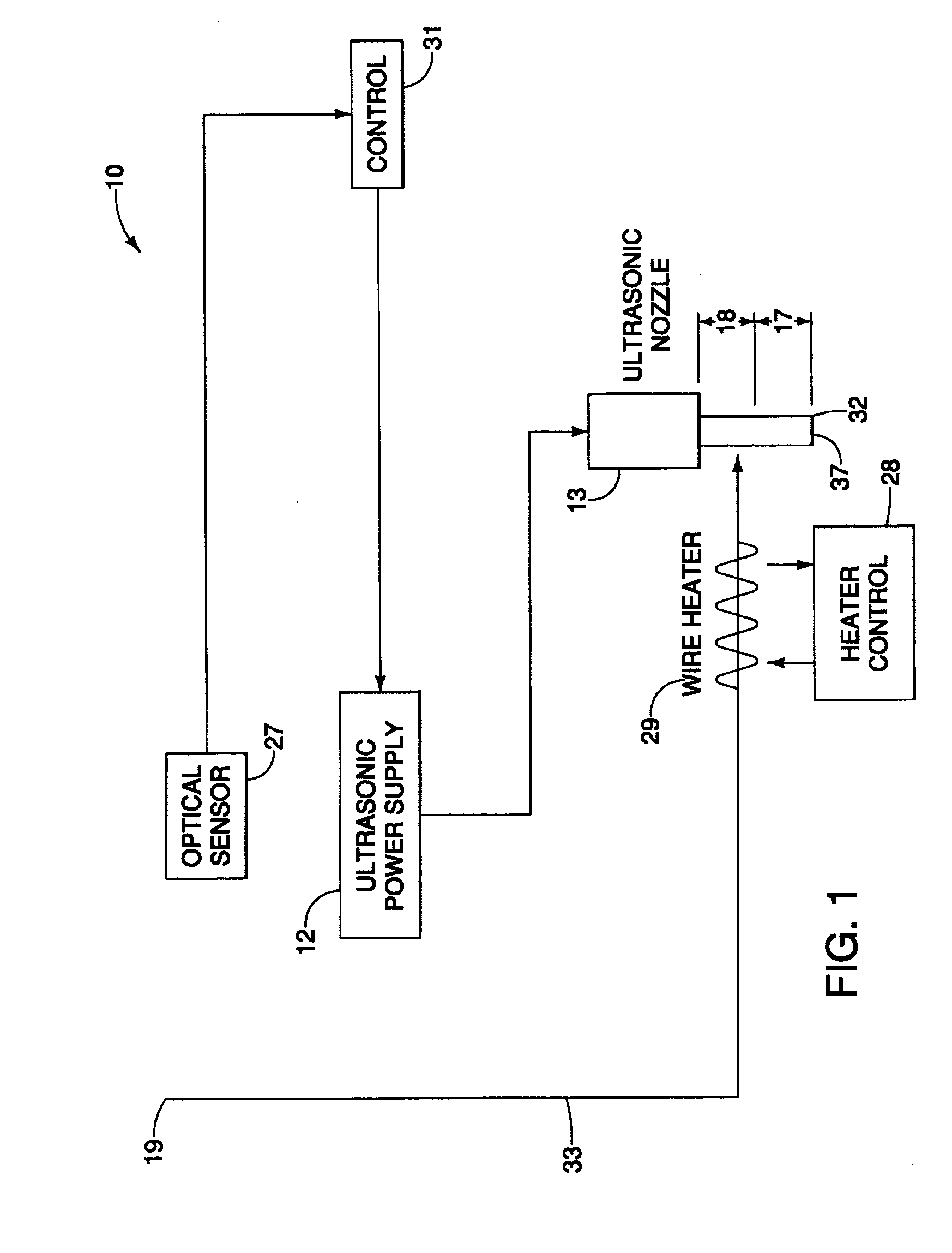

Image

  • Ultrasonic nozzle
  • Ultrasonic nozzle
  • Ultrasonic nozzle

Examples


example 1

[0127]

Operating Frequency20 kHzMaterial of ConstructionTitaniumNozzle length14 cmOrifice size3 mm in diameterAmplitude gain12Booster assemblyNot required

example 2

[0128]

Operating Frequency20 kHzMaterial of ConstructionTitaniumNozzle length14 cmOrifice size1 mm in diameterAmplitude gain4Booster assemblyrequired

example 3

[0129]

Operating Frequency20 kHzMaterial of ConstructionAluminumNozzle length14 cmOrifice sizeNo orifice, liquid supplied to thetip from the exterior wallAmplitude gain2Booster assemblyRequired

[0130]The dimensions and values disclosed herein are not to be understood as being strictly limited to the exact numerical values recited. Instead, unless otherwise specified, each such dimension is intended to mean both the recited value and a functionally equivalent range surrounding that value. For example, a dimension disclosed as “40 mm” is intended to mean “about 40 mm.”


PUM


Abstract

An ultrasonic nozzle for applying a coating to an exterior surface of a substrate. The ultrasonic nozzle has an ultrasonic nozzle having an amplitude. The amplitude is greater than 120 microns.

Description

CROSS REFERENCE TO RELATED APPLICATIONS[0001]This application claims priority to and the benefit of U.S. Provisional application 60 / 926,970, filed on Apr. 30, 2007, which is hereby incorporated by reference herein in its entirety.FIELD OF THE INVENTION[0002]This invention relates to an ultrasonic nozzle used to apply a fluid to a substrate.BACKGROUND OF THE INVENTION[0003]A wide variety of operations, especially food processing, involve the application of a fluid coating material. Conventionally, the fluid coating solution or slurry is applied to the food substrate with conventional spray nozzles that dispense the slurry in a spray pattern using only the hydrostatic pressure of the slurry supply to form the spray. While useful and effective, the ease of conventional hydrostatic slurry restrictive orifice discharge nozzles has numerous disadvantages.[0004]One disadvantage involves the difficulty of applying low flow rates, especially below 500 ml / min. The conventional hydrostatic pre...

Claims


Application Information

Patent Timeline
IPC IPC(8): B05B1/00
CPCA23L1/0061A23L1/0252B05B17/0623B05B17/063A23L5/32A23P20/18
Inventor QUAN, KE-MINGDECHERT, GARY JAMESWEN, LUFANGMORRISON, LOWEN ROBERTPEGOLI, RONALD EDWARDGLASSMEYER, STEPHEN ROBERT
Owner KELLOGG NORTH AMERICA
Why Eureka
Try Eureka