Dynamic ice cool storage method and apparatus thereof

A technology of ice storage and equipment, applied in the field of cold storage and refrigeration, can solve the problems of increasing thermal resistance, reducing the cooling coefficient of refrigerators, increasing costs, etc.

Inactive Publication Date: 2005-12-28
朱上翔 +1
View PDF0 Cites 7 Cited by
  • Summary
  • Abstract
  • Description
  • Claims
  • Application Information

AI Technical Summary

Problems solved by technology

However, the static ice-making method also has its own disadvantages: the thickening of the ice layer increases the thermal resistance, resulting in a decrease in the cooling coefficient (COP) of the refrigerator; the mutual adhesion of ice cubes in some static systems leads to blockage of waterways
Moreover, static ice storage generally requires a large number of coils for the refrigerant to flow through, and the brine (water or other liquid) outside the tubes is frozen for cold storage, which increases the cost, volume and control difficulty.

Method used


Image

  • Dynamic ice cool storage method and apparatus thereof
  • Dynamic ice cool storage method and apparatus thereof
  • Dynamic ice cool storage method and apparatus thereof

Examples


Embodiment 1

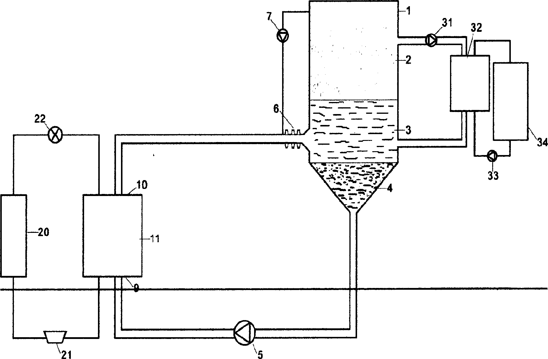
[0021] Fig. 1 is to take cooling through the refrigerant 4, the refrigerant 4 is transported to the heat exchanger 11 by the pump 5 through the transmission pipeline, the temperature of the input end 9 of the heat exchanger 11 is higher than 0°C, and the temperature of the output end 10 is lower than 0°C, due to the refrigerant The melting point of the refrigerant is lower than 0°C, and the refrigerant at the output end 10 is still in a liquid state, and the refrigerant in a liquid state below 0°C is transported back to the energy storage tank 1, and the refrigerant is evenly dispersed in the water layer 3 through the ultrasonic atomizing nozzle 6, The water around the refrigerant quickly absorbs the cooling capacity of the refrigerant, resulting in crystallization. These crystals are called ice crystals 2. The ice crystals float on the water surface due to their small specific gravity, while the refrigerant gradually sinks to the bottom of the tank due to their high specific gr...

Embodiment 2

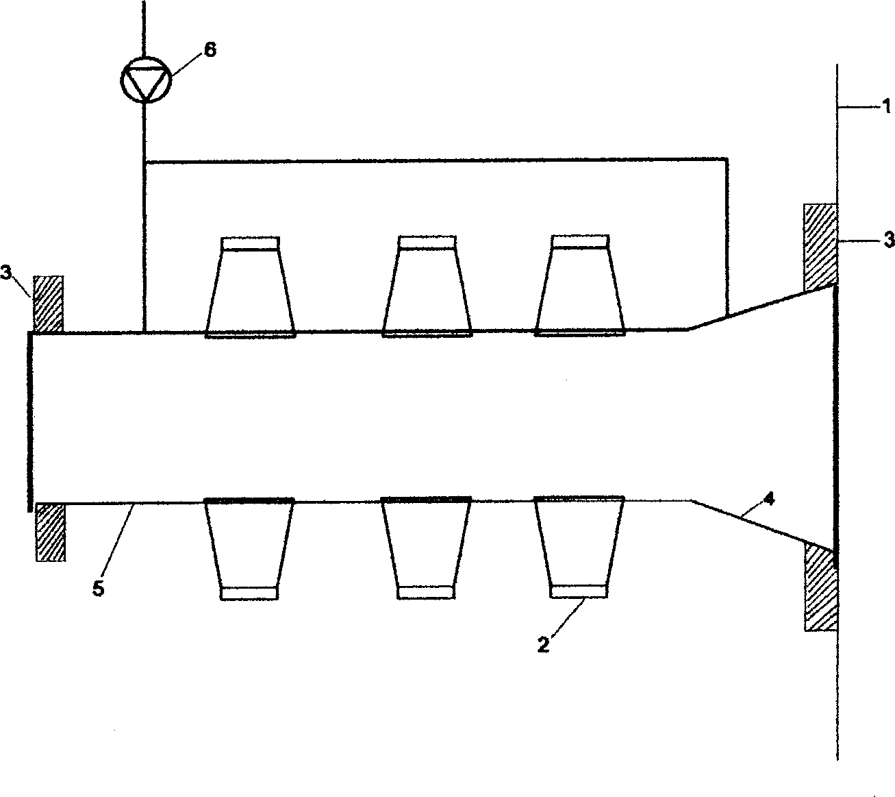
[0027] Figure 2 is the structural diagram of the ultrasonic nozzle, which is installed at the middle and lower entrance of the energy storage tank. The structure of the ultrasonic nozzle is composed of a pipeline 5, a plurality of ultrasonic transducers 2, a flange 3, a conical nozzle 4 and an air pump 6. The transducer 2 is installed on the conical nozzle 4 and the front end pipe wall of the nozzle. The ultrasonic wave emitted by the transducer creates an ultrasonic field in the liquid in the pipe, generating air bubbles to activate the refrigerant flowing through, making the particles smaller, increasing the exchange area between the refrigerant and water, and improving efficiency; and crushing the ice flakes in the refrigerant , to avoid pipeline blockage; at the same time prevent a large number of ice crystals generated by the nozzle from clogging the nozzle; more advantageously, due to the disturbance of the ultrasonic field, the refrigerant is quickly separated from the i...

Embodiment 3

[0029] Figure 3 is a specific application of an ice storage air conditioning system. The refrigeration unit 21, the condenser 20, the expansion valve 22 and the heat exchanger 11 form a refrigeration cycle. Through the heat exchanger 11, the refrigerant absorbs the cooling capacity and becomes a low-temperature refrigerant below 0°C. The water is fully mixed to produce a large number of ice crystals, which float on the water layer of the energy storage tank due to the buoyancy. into the heat exchanger 32 for heat exchange to complete the load refrigeration cycle.


PUM


Abstract

A method for accumulating cold by dynamic ice includes such steps as loading the mixture of water and the cold medium in the form of liquid colloid deposited under water in a conic energy accumulator, pumping said cold medium from the bottom of said conic energy accumulator into heat exchanger, heat exchanging for cooling it to the temp lower than zero deg.C, holding it in the form of liquid as its setting point is lower than zero deg.C, spraying it into upper water layer in said accumulator by ultrasonic nozzle, and crystallizing the water to form floating ice crystals while depositing said cold medium. Its apparatus is also disclosed.

Description

technical field [0001] The present invention relates to refrigeration and cold storage methods or systems, in particular to a dynamic ice storage method and equipment, and relates to the dynamic ice storage method and the structural design of ice crystal manufacturing equipment. Background technique [0002] The so-called ice storage is to store cold energy in the form of ice through refrigeration during the low power consumption period at night when the power load is very low. During the daytime peak period when the power load is high, the stored energy is released to meet the needs of the building's air conditioning load. At the same time, in the spring and autumn when the air-conditioning load is small, reduce the opening of the refrigerator, try to melt the ice and release the cold, and meet the air-conditioning load. Ice storage air conditioner is an effective method to "transfer power load" or "balance power load". [0003] Dynamic ice storage is relative to static i...

Claims


Application Information

Patent Timeline
Patent Type & Authority Applications(China)
IPC IPC(8): F24F5/00
CPCY02E60/14
Inventor 朱上翔谢一鹏
Owner 朱上翔
Why Eureka
Try Eureka