Piezoelectric body, piezoelectric device, and liquid discharge apparatus

a piezoelectric device and piezoelectric body technology, applied in the direction of device details, device details, generators/motors, etc., can solve the problems of inability to obtain sufficient piezoelectric effect, high applied electric field on the piezoelectric body, and limited strain displacement of the piezoelectric device, etc., to achieve the effect of enhancing piezoelectric performan

Active Publication Date: 2008-10-30
FUJIFILM CORP
View PDF4 Cites 47 Cited by
  • Summary
  • Abstract
  • Description
  • Claims
  • Application Information

AI Technical Summary

Benefits of technology

[0017]The primary object of the present invention is to provide a piezoe...

Problems solved by technology

However, in cases where the aforesaid piezoelectric effect of the ferroelectric substances is merely utilized, strain displacement of the piezoelectric device is limited.
However, in the cases of the piezoelectric devices having the reduced thicknesses, if a voltage is applied across the piezoelectric device in the same manner as that for the conventional piezoelectric devices, the applied electric field exerted upon the piezoelectric body will become high.
Therefore, in such cases, if the same material design as in the conventional piezoelectric devices is made directly, a sufficient piezoelectric effect will not be capable of being obtained.
However, as for the piezoelectric devices having the reduced thicknesses, in cases where the voltage is applied across the piezoelectric device in the same manner as that for the conventional piezoelectric devices, the applied electric field exerted upon the piezoelectric body becomes high.
Specifically, in such cases, the substantial piezoelectric constant is smaller than the piezoelectric constant with respect to the applied electric field range of 0 to Ex, and the piezoelectric characteristics, which the piezoelectric devices originally have, are not capable of being ut...

Method used


Image

  • Piezoelectric body, piezoelectric device, and liquid discharge apparatus
  • Piezoelectric body, piezoelectric device, and liquid discharge apparatus
  • Piezoelectric body, piezoelectric device, and liquid discharge apparatus

Examples


example 1

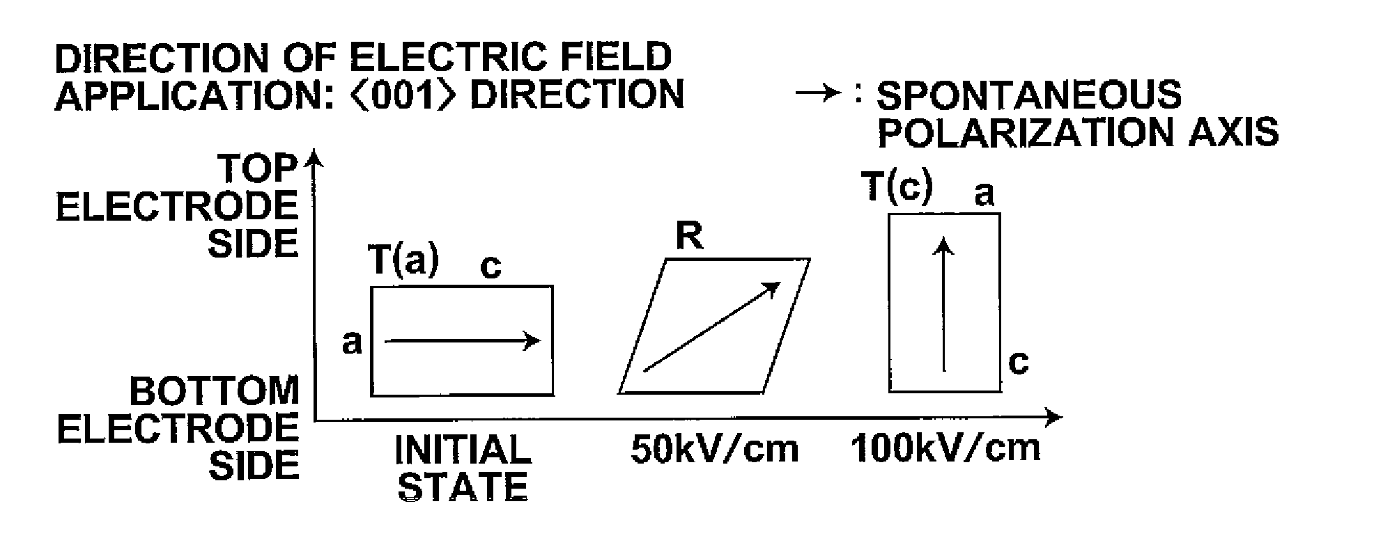
[0139]An Si wafer was prepared as a base plate. Also, an Ir bottom electrode having a thickness of 150 nm, an Nb-doped PZT piezoelectric body film having a thickness of 5.0 μm, and a Pt top electrode having a thickness of 150 nm were formed successively on a surface of the base plate by use of a sputtering technique. In this manner, a piezoelectric device in accordance with the present invention was obtained. Each of the bottom electrode, the piezoelectric body film, and the top electrode was formed over the entire area of the base plate. The composition of the piezoelectric body film was set such that the Zr / (Zr+Ti) molar ratio was equal to 0.52, and such that the Nb doping concentration at the B site was equal to 13 mol %.

[0140]With respect to the piezoelectric body film described above, synchrotron X-ray diffraction (XRD) measurements were performed. FIG. 5 shows XRD patterns in an initial state (i.e., in a state free from electric field application), in a state in which an elect...


PUM

PropertyMeasurementUnit
Temperatureaaaaaaaaaa
Piezoelectricityaaaaaaaaaa

Abstract

A piezoelectric body contains a ferroelectric substance phase having characteristics such that, in cases where an applied electric field is increased from the time free from electric field application, phase transition of the ferroelectric substance phase to a ferroelectric substance phase of a different crystal system occurs at least two times. The piezoelectric body should preferably be actuated under conditions such that a minimum applied electric field Emin and a maximum applied electric field Emax satisfy Formula (1):
Emin<E1<Emax   (1)
wherein the electric field E1 represents the electric field at which the first phase transition of the ferroelectric substance phase begins.

Description

BACKGROUND OF THE INVENTION[0001]1. Field of the Invention[0002]This invention relates to a piezoelectric body containing a ferroelectric substance phase having characteristics such that the ferroelectric substance phase is caused by electric field application to undergo phase transition. This invention also relates to a piezoelectric device provided with the piezoelectric body, and a liquid discharge apparatus provided with the piezoelectric device.[0003]2. Description of the Related Art[0004]Piezoelectric devices provided with a piezoelectric body, which has piezoelectric characteristics such that the piezoelectric body expands and contracts in accordance with an increase and a decrease in electric field applied across the piezoelectric body, and electrodes for applying the electric field across the piezoelectric body have heretofore been used as actuators to be loaded on ink jet type recording heads, and the like.[0005]As piezoelectric body materials, there have heretofore been k...

Claims


Application Information

Patent Timeline
IPC IPC(8): H01L41/187C04B35/01H01L41/04
CPCB41J2/14233B41J2/155H01L41/187H01L41/1876H01L41/316H01L41/0973H10N30/1051H10N30/2047H10N30/8554H10N30/076
Inventor SAKASHITA, YUKIOSASAKI, TSUTOMUOKAMOTO, YUUICHINAKAI, MUNENORI
Owner FUJIFILM CORP
Why Eureka
Try Eureka