Coupled lamp driving device

a driving device and lamp technology, applied in the direction of gas discharge lamp usage, climate sustainability, light sources, etc., can solve the problems of poor coupling effect, high leakage of leakage transformers, high temperature, etc., and achieve the effect of balancing a plurality of lamps, maintaining a uniform luminance over the lamps, and increasing the coupling coefficien

Inactive Publication Date: 2008-10-30
LOGAH TECH CORP
View PDF10 Cites 3 Cited by
  • Summary
  • Abstract
  • Description
  • Claims
  • Application Information

AI Technical Summary

Benefits of technology

[0010]It is, therefore, an object of the present invention to provide a coupled lamp driving device capable of effectively balancing a plurality of lamps and thus maintaining a uniform luminance over the lamps.
[0011]It is another object of the present invention to provide a coupled lamp driving device, in which a coupled transformer is used. Since it is not required to have a leakage of the transformer to filter owing to the provision of the coupled transformer, the larger the coupling coefficient is, the efficiency the better. Meanwhile, a number of coils the transformer needs not to be large and will be feasible as long as the magnetic flux of the transformer is acceptable. Since the fewer coils results in the less internal resistance, the overall efficiency can be enhanced.
[0012]It is still another object of the present invention to provide a coupled lamp driving device, which has an improved stability and lifetime and a lowered cost, dimension of the transformer spacial arrangement.
[0013]In accordance with the present invention, a coupled lamp driving device comprises an alternating current (AC) power supply providing a sine-wave to two ends of each of a plurality of coupled transformers each having a primary side connected to each other at a primary side thereof and a secondary side; the plurality of coupled transformers connected to each other at the primary side thereof directing the sine-wave signal from the AC power supply to the two sides of the primary side of each of the coupled transformers and connected to an end of one of a plurality of lamps at one end of the secondary side thereof and connected to a reference level at the other end thereof; and the plurality of lamps each having the other end connected to a reference level. Since the primary sides of the coupled transformers are connected in series, a current flown on the primary side of each of the coupled transformers is equal to each other, respectively. Further, since the numbers of coils of the primary and secondary sides, respectively, are equal to each other, currents flown on the secondary side of each of the coupled transformers are also the same. Therefore, the luminance of each of the plurality of lamps can be maintained uniformly.

Problems solved by technology

In this regard, the leakage transformer requires high leakage and high number of coils to operate.
However, the higher leakage means the coupling effect is poorer.
Both the higher leakage and coil number contribute to a power loss and thus result in a high temperature.
Therefore, the leakage transformer has to be considered in its specification and cost in the design of the conventional lamp driving device, and thus the leakage transformer will often form a limitation in the conventional lamp driving device.
In view of the above, there exist many disadvantages in the prior art and am improved lamp driving device has to be proposed.

Method used


Image

  • Coupled lamp driving device
  • Coupled lamp driving device
  • Coupled lamp driving device

Examples


first embodiment

[0026]Referring to FIG. 3, a circuit diagram of a coupled lamp driving device according to the present invention is shown therein. As shown, the lamp driving device 3 comprises an alternating current (AC) power supply 31, which provides a sine-wave signal to two ends of each of a plurality of coupled transformers 32 connected to each other at their primary sides. Through the plurality of coupled transformers 32 connected at their primary sides, the sine-wave signal is directed to the two ends of the primary side of each of the coupled transformer 32. A secondary side of the coupled transformer 32 is connected to a high voltage end of a lamp 33 at one end, and connected to a reference level at the other end. Since the primary sides of the coupled transformers 32 are connected in series, a current flown on the primary side of each of the coupled transformers 32 is equal to each other, respectively. Further, since the numbers of coils of the primary and secondary sides, respectively, a...

second embodiment

[0028]Referring to FIG. 4, a circuit diagram of the coupled lamp driving device according to the present invention is shown therein. As shown, the coupled lamp driving device 4 comprises a direct current a direct current (DC) power supply 41 which outputs a DC power. The square-wave switch 42 is used to receives the DC power, convert the DC power into a square-wave signal and then a sine-wave signal through an inductor 43 and a capacitor 44, and then provides the sine-wave signal to two ends of each of a plurality of coupled transformers 45 connected at a primary side thereof.

[0029]A square-wave controller 46 is used to output a control signal to the square-wave switch 42.

[0030]Each of the plurality of coupled transformers 45 is connected to each other at the primary side thereof and directs the sine-wave signal obtained through the inductor 43 and the capacitor 44 to the two ends of the primary side of each of the plurality of coupled transformers 45 and connected to one end, a hig...

third embodiment

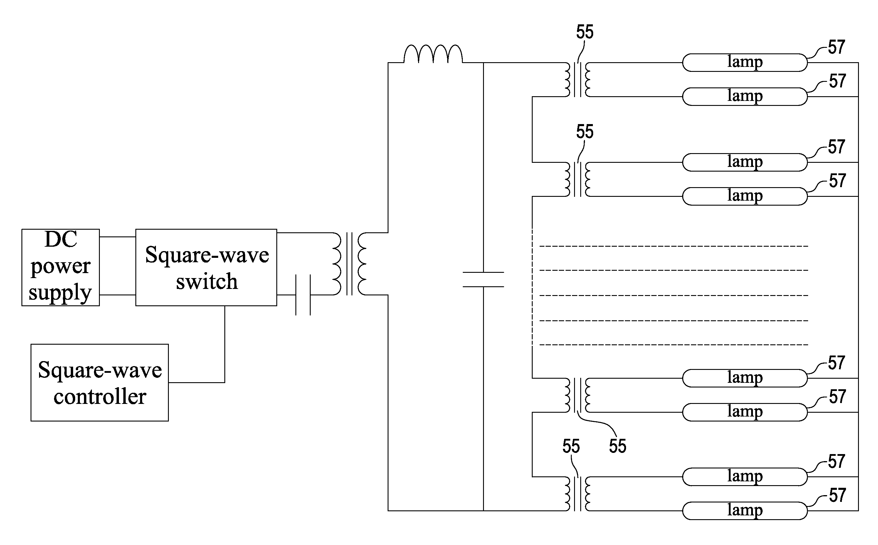
[0034]FIG. 6 is a circuit diagram of the coupled lamp driving device according to the present invention. As shown, the coupled lamp driving device. As shown the coupled lamp driving device 50 comprises a direct current (DC) power supply 51, which outputs a DC power;

[0035]A square-wave switch 52 is used to receive the DC power, convert the DC power into a square-wave signal and then output the square-wave signal.

[0036]The driving transformer 53 is used to receive the square-wave signal from the square-wave switch 52 at a primary side thereof. Between the square-wave switch 52 and the driving transformer 53, a capacitor 58 may be disposed for blocking a DC noise. Further, the driving transformer 53 converts the square-wave signal into a sine-wave signal through a leakage thereof (not shown) and a capacitor 54, and provides the sine-wave signal to two ends of each of a plurality of coupled transformers 55 connected to each other at a primary side thereof.

[0037]A square-wave controller ...


PUM


Abstract

A coupled lamp driving device is described, comprising an alternating current (AC) power supply providing a sine-wave to two ends of each of a plurality of coupled transformers each having a primary side connected to each other at a primary side thereof and a secondary side; the plurality of coupled transformers connected to each other at the primary side thereof directing the sine-wave signal from the AC power supply to the two sides of the primary side of each of the coupled transformers and connected to an end of one of a plurality of lamps at one end of the secondary side thereof and connected to a reference level at the other end thereof, and the plurality of lamps each having the other end connected to a reference level. Since the primary sides of the coupled transformers are connected in series, a current flown on the primary side of each of the coupled transformers is equal to each other, respectively. Further, since the numbers of coils of the primary and secondary sides, respectively, are equal to each other, currents flown on the secondary side of each of the coupled transformers are also the same. Therefore, the luminance of each of the plurality of lamps can be maintained uniformly.

Description

BACKGROUND OF THE INVENTION[0001]1. Field of the Invention[0002]The present invention relates to a coupled lamp driving device, and particularly to a coupled lamp driving device capable of maintaining a uniform luminance among lamps used in a liquid crystal display (LCD) backlight source.[0003]2. Description of the Prior Art[0004]Referring to FIGS. 1A and 1B, in which diagrams for illustrating a circuit analysis and an analysis principle of a leakage transformer applied into a lamp driving device. As shown, the leakage transformer used in the lamp driving device may be considered as a combination of an ideal transformer 21 and a leakage of transformer 22. In the lamp driving device, a square wave signal is generated and then boosted in voltage through the ideal transformer 21. Next, the boosted square wave signal is filtered by the leakage of transformer 22 and a capacitor 16, through which a sinusoidal wave is generated, which is subsequently supplied to a lamp 11. This principle o...

Claims


Application Information

Patent Timeline
Patent Type & Authority Applications(United States)
IPC IPC(8): H05B41/36
CPCH05B41/282Y02B20/183Y02B20/00
Inventor HSU, CHENG-CHIACHANG, TENG-KANGPAN, YU-CHENG
Owner LOGAH TECH CORP
Why Eureka
Try Eureka