Method for controlling high-frequency radiator

a high-frequency radiator and control method technology, applied in the direction of electrification characteristics varying frequency control, electrical/magnetic/electromagnetic heating, sustainable buildings, etc., can solve the problems of very likely to be broken and extremely likely to be broken, so as to improve the operation reliability of the high-frequency radiator and prevent overheating of the solid-state oscillator

Inactive Publication Date: 2008-10-30
PANASONIC CORP
View PDF11 Cites 25 Cited by
  • Summary
  • Abstract
  • Description
  • Claims
  • Application Information

AI Technical Summary

Benefits of technology

[0018]In this way, the temperature of the solid-state oscillator is sensed during the operation of the high-frequency radiator, thereby preventing overheating of the solid-state oscillator and improving the operation reliability of the high-frequency radiator.

Problems solved by technology

However, since a solid-state oscillator made of a semiconductor is very likely to be broken, it is extremely likely to be broken during the sensing of the operating state of the high-frequency radiator.

Method used


Image

  • Method for controlling high-frequency radiator
  • Method for controlling high-frequency radiator
  • Method for controlling high-frequency radiator

Examples


embodiment 1

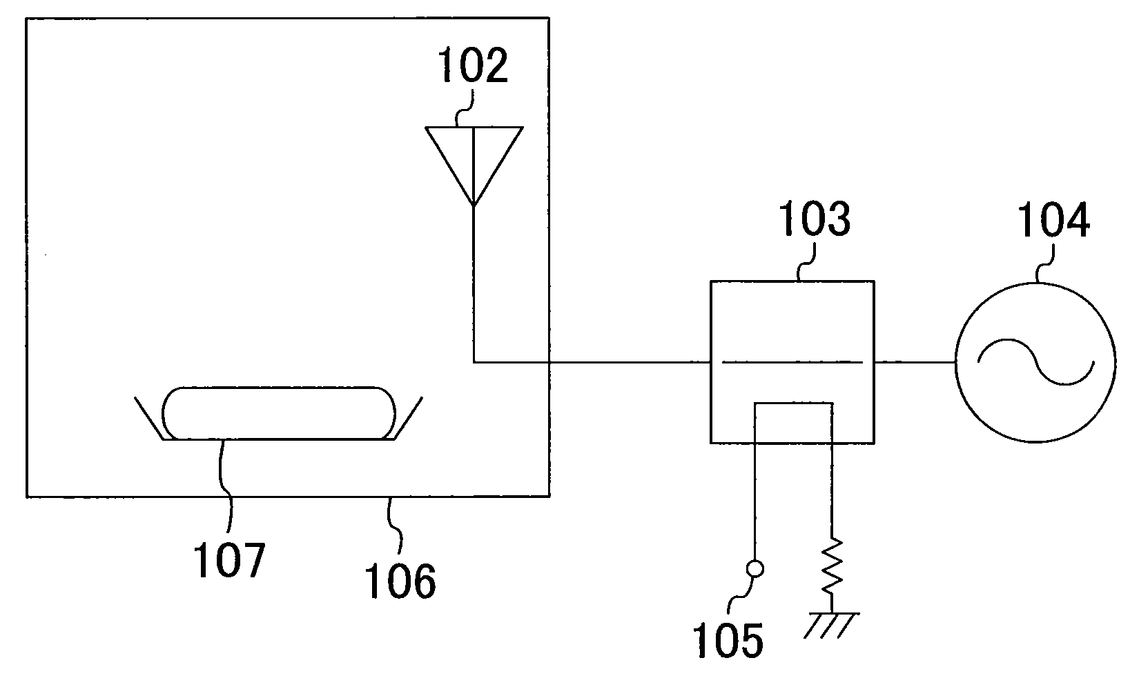
[0032]FIG. 1 is a diagram schematically illustrating the basic configuration of a high-frequency heater according to a first embodiment of the present invention. As illustrated in FIG. 1, the high-frequency heater of this embodiment includes a solid-state oscillator 104 for generating a high-frequency radiation, a directional coupler 103 for transmitting the high-frequency radiation generated by the solid-state oscillator 104, a heating chamber 106 for accommodating an object 107 to be heated (hereinafter, referred to as a “to-be-heated object 107”), and an antenna 102 placed in the heating chamber 106 to apply the high-frequency radiation transmitted through the directional coupler 103 to the heating chamber 106. The directional coupler 103 is provided with a monitor terminal 105 for monitoring high-frequency power propagating through the directional coupler 103 in the inverse direction (toward the solid-state oscillator 104). As long as the high-frequency radiation output by the s...

first specific example

of Method for Controlling High-Frequency Heater

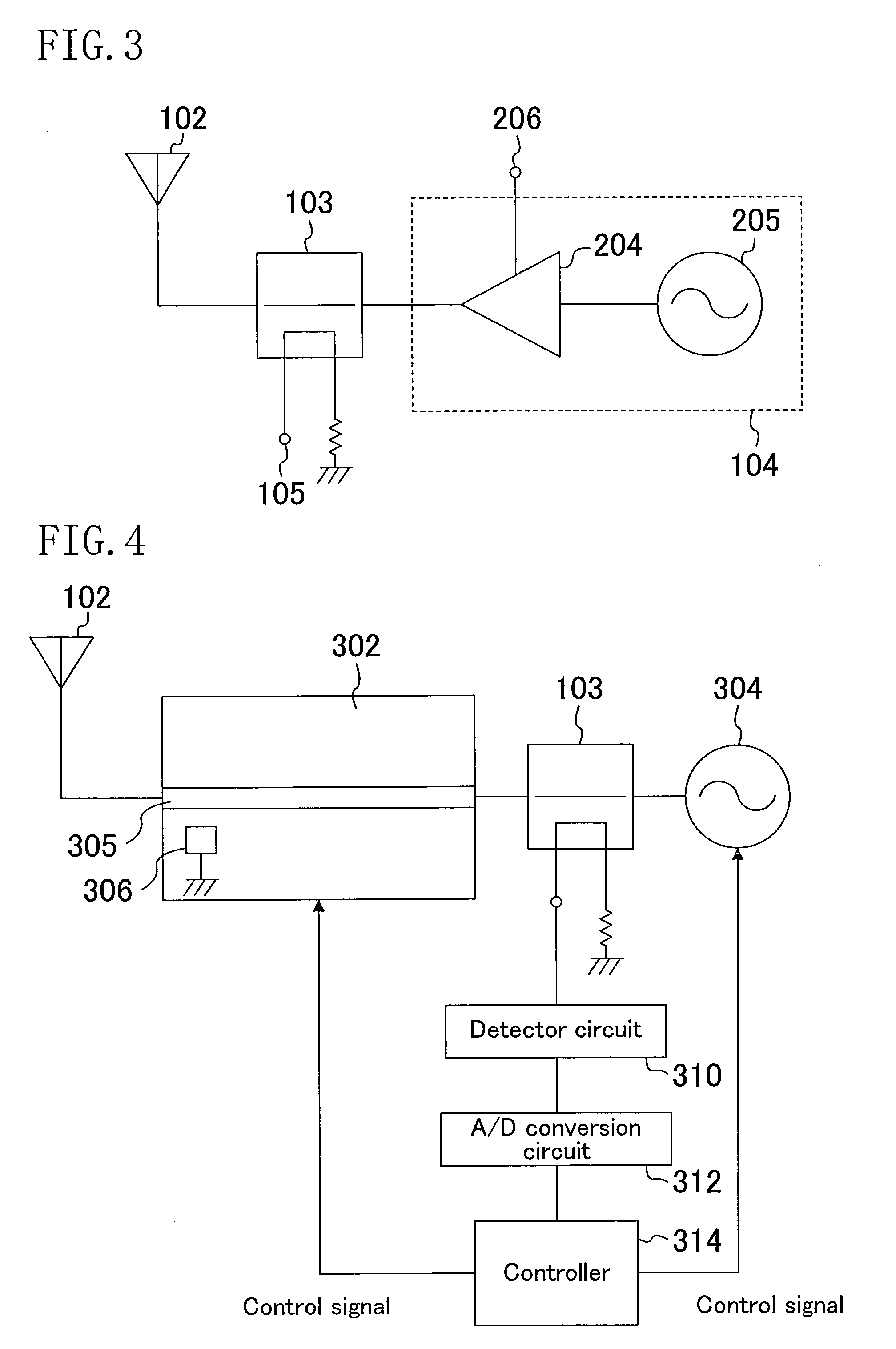
[0044]FIG. 3 is a diagram schematically illustrating a high-frequency heater according to a first specific example of the first embodiment. The high-frequency heater illustrated in FIG. 3 has basically the same configuration as that illustrated in FIG. 1. Meanwhile, in the first specific example, the solid-state oscillator 104 is composed of an oscillator 205 and an amplifier 204 connected to a bias terminal 206. In the solid-state oscillator 104, a high-frequency radiation generated by the oscillator 205 is amplified by the amplifier 204 and guided through the directional coupler 103 to the antenna 102.

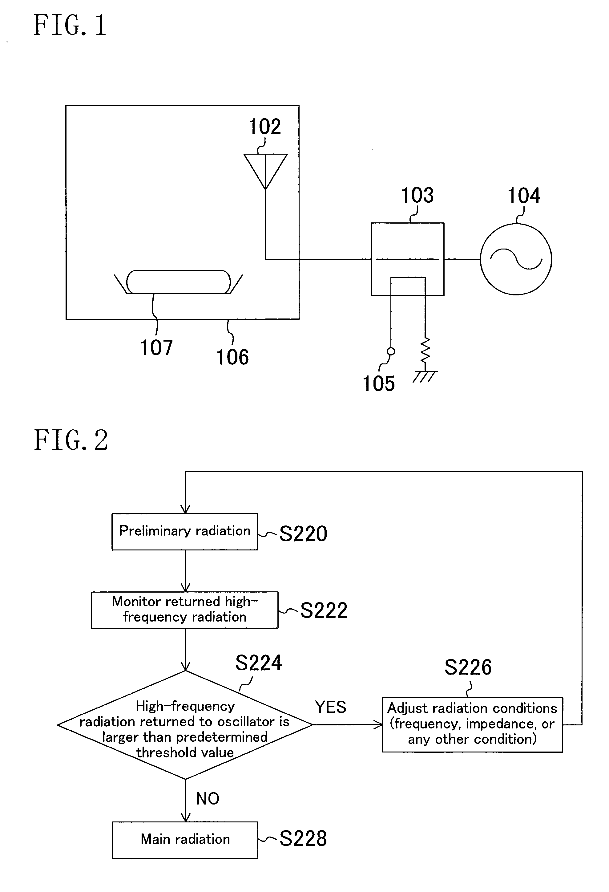
[0045]The operation of the high-frequency heater according to the first specific example is controlled in accordance with the procedure of steps S220 through S228 illustrated in FIG. 2.

[0046]More particularly, the step of applying a preliminary high-frequency radiation is initially performed as step S220. Next, in step S222, part of the ...

second specific example

of Method for Controlling High-Frequency Heater

[0050]FIG. 4 is a diagram schematically illustrating a high-frequency heater according to a second specific example of the first embodiment. The high-frequency heater illustrated in FIG. 4 has basically the same configuration as that illustrated in FIG. 1. However, in order to adjust the high-frequency radiation / propagation conditions, it further includes a detector circuit 310, an A / D (analog / digital) conversion circuit 312, a controller 314, and a slide-screw tuner 302.

[0051]In other words, the high-frequency heater of this specific example includes the antenna 102, the slide-screw tuner 302, the directional coupler 103, a solid-state oscillator 304, the detector circuit 310, the A / D conversion circuit 312, and the controller 314. A high-frequency radiation generated by the solid-state oscillator 304 is guided through the directional coupler 103 and the slide-screw tuner 302 to the antenna 102.

[0052]The slide-screw tuner 302 includes,...


PUM


Abstract

A method for controlling a high-frequency radiator includes the steps of: (a) applying a high-frequency radiation through the solid-state oscillator and the antenna; (b) sensing part of the high-frequency radiation returned from the antenna to the solid-state oscillator; (c) adjusting radiation/propagation conditions for the high-frequency radiation on the basis of the sensed results in the step (b), the high-frequency radiation propagating from the solid-state oscillator to the antenna; and (d) after the step (c), applying the high-frequency radiation through the solid-state oscillator and the antenna to a target object. In the step (c), the oscillation frequency of the solid-state oscillator, the power of the high-frequency radiation applied by the solid-state oscillator, the power supply voltage supplied to the solid-state oscillator, the impedance match between the output impedance of the solid-state oscillator and the impedance of the antenna, or any other condition is changed.

Description

BACKGROUND OF THE INVENTION[0001](1) Field of the Invention[0002]The present invention relates to high-frequency heaters, and more particularly relates to a method for controlling a high-frequency heater when a high-frequency radiation with high power is applied to an object to be heated.[0003](2) Description of Related Art[0004]Methods for heating a high-permittivity object to be heated include a commonly used method in which the power of a microwave, a kind of an electromagnetic wave, is utilized.[0005]In order to produce such a microwave, a magnetron having an electron tube is caused to oscillate, and an oscillatory output radiation is applied to a cavity in the magnetron, thereby heating an object to be heated. For example, for a microwave oven, the above-described cavity corresponds to a space which is called an oven and into which an object to be heated is inserted. The anode voltage of the magnetron is high so that a voltage of approximately several thousand volts is applied ...

Claims


Application Information

Patent Timeline
Patent Type & Authority Applications(United States)
IPC IPC(8): H03L7/099
CPCH03H7/40H05B6/686H05B6/705Y02B40/143Y02B40/146Y02B40/00
Inventor YAHATA, KAZUHIROUNO, TAKASHISAKAI, HIROYUKITANAKA, TSUYOSHIUEDA, DAISUKE
Owner PANASONIC CORP
Why Eureka
Try Eureka