Adjustable antenna and methods

Active Publication Date: 2008-10-30
PULSE FINLAND
View PDF55 Cites 64 Cited by
  • Summary
  • Abstract
  • Description
  • Claims
  • Application Information

AI Technical Summary

Benefits of technology

[0010]In another aspect of the invention, an adjustable antenna is disclosed. In one embodiment, the antenna comprises: a radiator electrically coupled to an adjusting circuit, said adjusting circuit comprising a plurality of reactive circuits disposed between a feed conductor and a signal ground. Each of said plurality of reactive circuits generates a unique resonance frequency for said antenna.
[0011]In one variant, the antenna further comprises an antenna switch, said antenna switch implementing time divisional sharing between a plurality of transmit/receive components. The plurality of transmit/receive components comprise for example a first transmitter and receiver for a first system, and a second transmitter and receiver for a second, different system.
[0012]In another variant, said adjusting circuit further comprises at least one switch coupled to said plurality of reactive circuits, said at least one switch electrically coupled to a control feed. Signals received via said contr

Problems solved by technology

This is due in part to physically short tr

Method used


Image

  • Adjustable antenna and methods
  • Adjustable antenna and methods
  • Adjustable antenna and methods

Examples


Embodiment Construction

[0047]Reference is now made to the drawings wherein like numerals refer to like parts throughout.

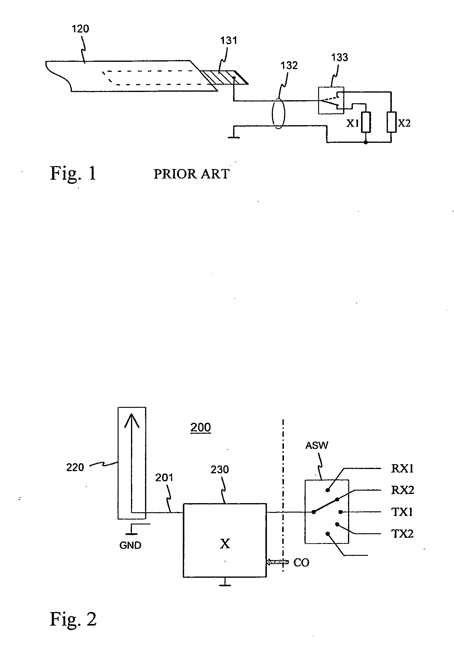
[0048]FIG. 1 was already described in conjunction with the description of the prior art.

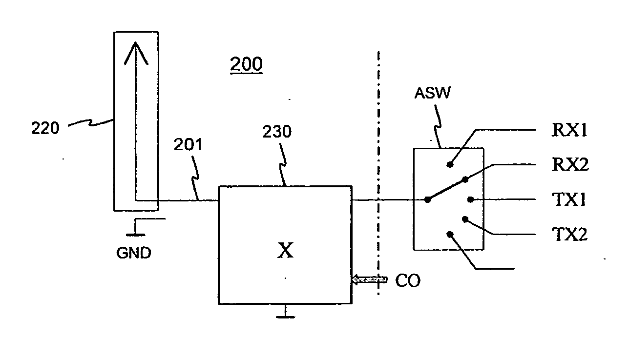
[0049]FIG. 2 shows the principled structure of an antenna according to the invention as a simple block diagram. The radiator 220 of an antenna 200 is of monopole type. Also the feed conductor 201 and the adjusting circuit 230 of the antenna are here included in the antenna. Naturally also the common signal ground GND, necessary in the function of the structure, belongs to it. The feed conductor has been connected to the radiator at its one end and to the rest of the radio device in question at its other end. In the example of FIG. 2 the radio device has the transmitters TX1, TX2 and receivers RX1, RX2 in compliance with two different systems, and its function is time divisional. For this reason the feed conductor is connected the transmitters and receivers through the antenna switch ASW. The adjusting...


PUM


Abstract

An adjustable monopole antenna especially intended for the mobile terminals. The adjusting circuit (930) of the antenna is located between the radiator (920) and the antenna port of a radio device and forms, together with the antenna feed conductor (901), a feed circuit. This circuit comprises an adjustable reactance between the feed conductor and the ground in series with the feed conductor or in both of those places. For example, the feed conductor can be connected by a multi-way switch to one of alternative transmission lines, which are typically short-circuited or open at their tail end and shorter than the quarter wave, each line acting for a certain reactance. The antenna operating band covers at a time only a part of the frequency range used by one or two radio systems, in which case the antenna matching is easier to arrange than of a real broadband antenna. The space required for both the radiator and the adjusting circuit is relatively small. There is no need to arrange a coupling to the radiator for the antenna adjusting, which means a simpler antenna structure and thus savings in production costs.

Description

PRIORITY AND RELATED APPLICATIONS[0001]This application claims priority to International PCT Application No. PCT / FI2006 / 050418 entitled “Adjustable antenna” having an international filing date of Sep. 28, 2006, which claims priority to Finland Patent Application No. 20065116 of the same title filed Feb. 15, 2006, as well as Finland Patent Application No. 20055554 filed Oct. 14, 2005, each of the foregoing incorporated herein by reference in its entirety. This application is related to co-owned and co-pending U.S. patent application Ser. No. 12 / 083,129 filed Apr. 3, 2008 entitled “Multiband Antenna System And Methods” (Attorney docket No. LKP.014A / OP101722), Ser. No. 12 / 080,741 filed Apr. 3, 2008 entitled “Multiband Antenna System and Methods” (Attorney docket No. LKP.015A / OP101819), Serial No. 12 / ______ filed Apr. 10, 2008 entitled “Internal Antenna and Methods” (Attorney docket No. LKP.016A / OP101815), Ser. No. 12 / 009,009 filed Jan. 15, 2008 and entitled “Dual Antenna Apparatus And ...

Claims


Application Information

Patent Timeline
IPC IPC(8): H01Q1/50H01Q5/15
CPCH01Q1/241H01Q9/42H01Q9/0442H01Q1/243H01Q9/30H01Q5/10H04B1/006
Inventor MILOSAVLJEVIC, ZLATOLJUBISOHATALA-LEHMIKANGAS, ANNEMIKKOLA, JYRKI
Owner PULSE FINLAND
Why Eureka
Try Eureka