Filter for x-ray radiation, and an arrangement for using filtered x-ray radiation for excitation

a filter and radiation technology, applied in the field of x-ray fluorescence analysis, can solve problems such as difficult spectral deconvolution

Inactive Publication Date: 2008-10-30
HITACHI HIGH TECH ANALYTICAL SCI FINLAND OY
View PDF1 Cites 21 Cited by
  • Summary
  • Abstract
  • Description
  • Claims
  • Application Information

AI Technical Summary

Benefits of technology

[0017]Simultaneously, the atoms of the lighter element will experience excitation and emit characteristic X-rays at K- and L-line energies. If a layer of a suitably selected heavier element, such as rhodium (Rh) or palladium (Pd), is placed between the lighter element layer and a sample, the same effect will be repeated with different energies: some overall absorption will occur in the subsequent layer, but most of all it will absorb the characteristic peaks of the lighter element, and give rise to new characteristic peaks at the L- and possibly K-line energies of the heavier material.
[0018]It has been found that it is possible to select the materials and layer thicknesses in a suitable manner, so that the excitation radiation that eventually hits the sample contains a significant amount of the high-energy bremsstrahlung combined with the advantageously located characteristic peaks of the heavier filtering element. One exemplary combination is a 20 micrometers thick Ni or Cu layer followed by a 3.5 micrometers thick Rh or Pd layer. The layers may be mechanically separate from each other, or they may be combined into a single mechanical entity. A support layer or a number of support layers made of material essentially transparent to X-rays may be used to mechanically reinforce the structure. At least one of the layers may be placed into a movable filter changer, with which it can be moved in and out from between the X-ray source and the sample.

Problems solved by technology

However, with a W anode the Compton scatter peaks are relatively close to the coherent scatter peaks, which makes spectrum deconvolution difficult.

Method used


Image

  • Filter for x-ray radiation, and an arrangement for using filtered x-ray radiation for excitation
  • Filter for x-ray radiation, and an arrangement for using filtered x-ray radiation for excitation
  • Filter for x-ray radiation, and an arrangement for using filtered x-ray radiation for excitation

Examples


Embodiment Construction

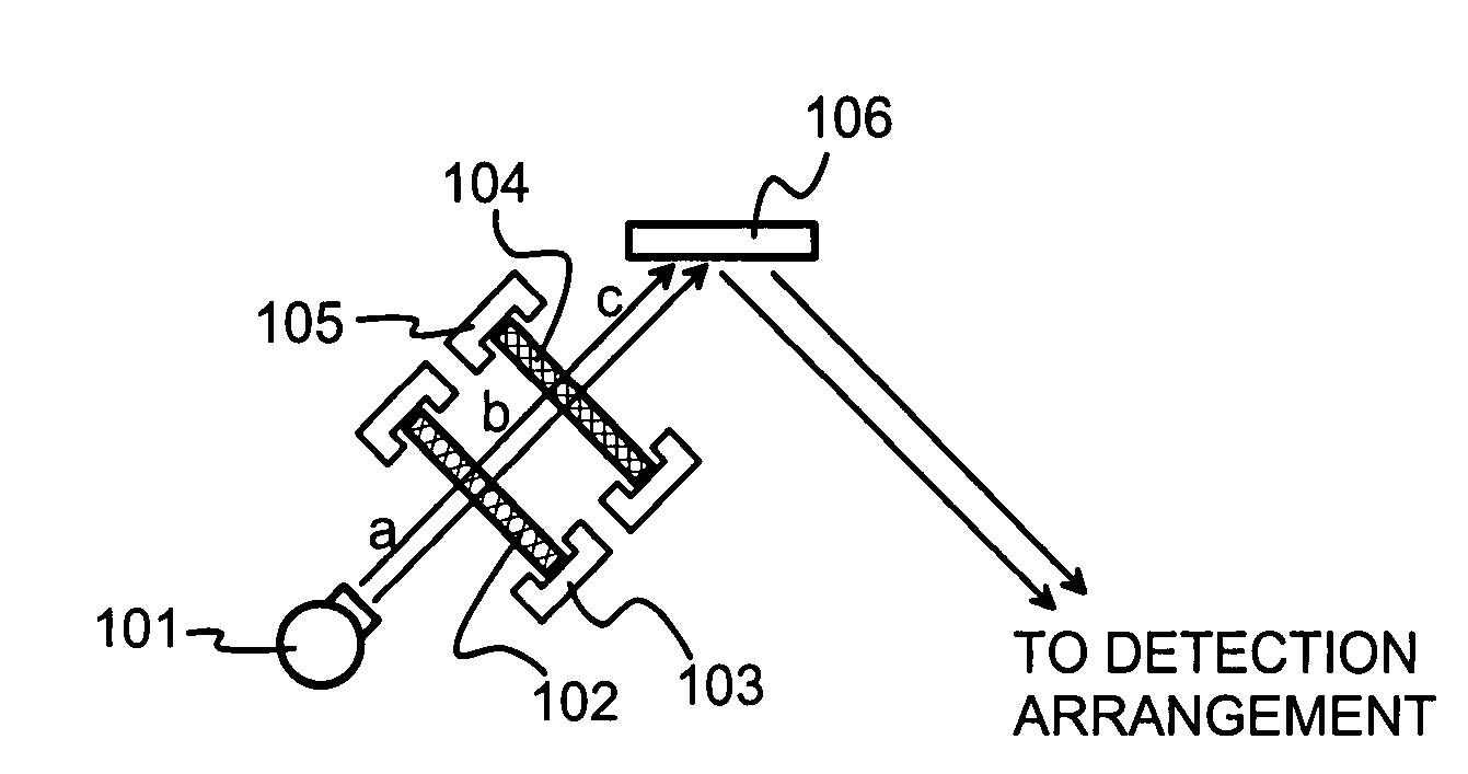
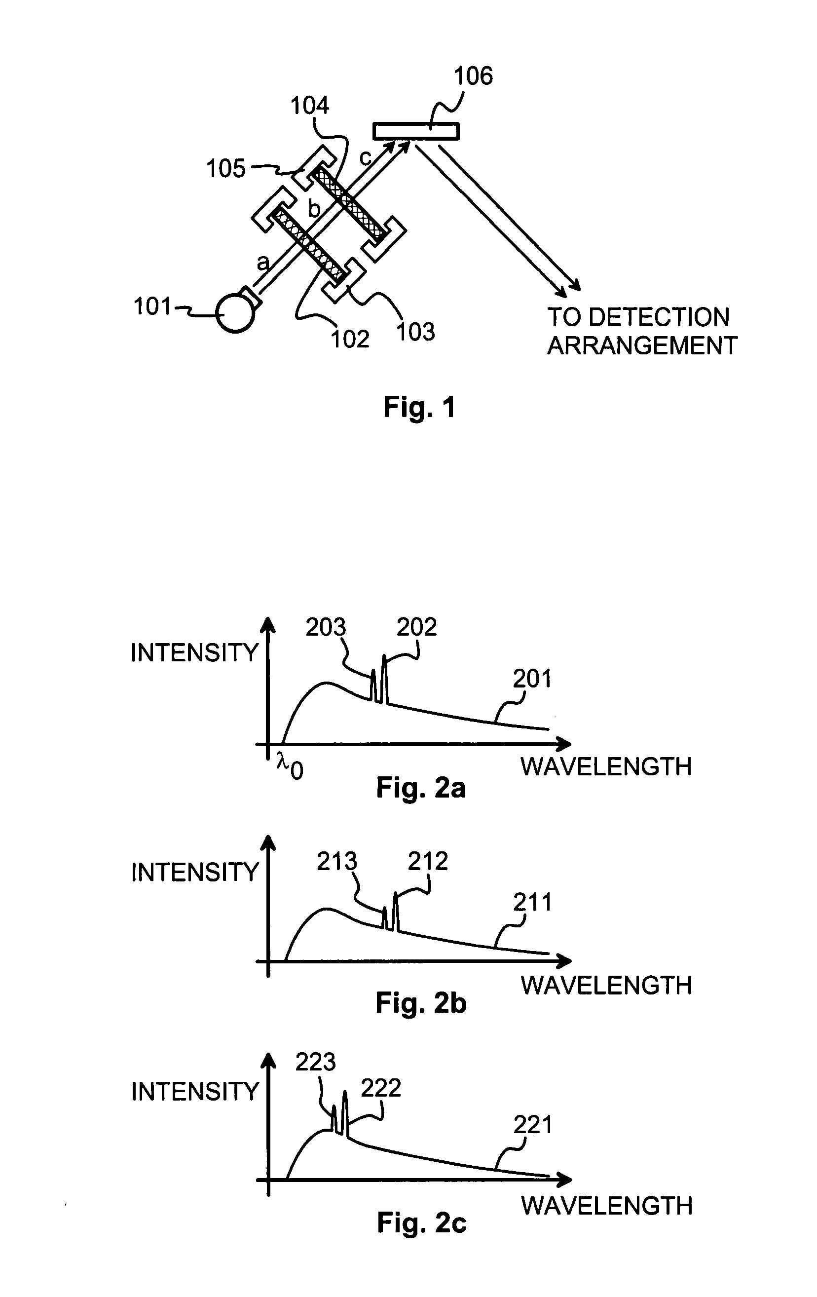
[0027]FIG. 1 illustrates schematically certain parts of an X-ray fluorescence analyzer device. An X-ray tube 101, which here is schematically shown as being of the side window type but which could also be of the end window type, acts as the source of incident X-rays. FIG. 2a illustrates schematically the intensity of the incident X-rays at location a in FIG. 1 as a function of wavelength. The continuous curve 201 illustrates the bremsstrahlung part of the incident X-rays. The shortest wavelength limit λ0 comes from the acceleration voltage of the X-ray tube 101, and any characteristic peaks (of which exemplary peaks 202 and 203 are shown in FIG. 2a) correspond to the electron shell structure of the anode material used in the X-ray tube 101. Here we assume that the anode material is tungsten, and the peaks 202 and 203 occur at 1.48 and 1.28 ångströms corresponding to the L-line energies 8.39 keV and 9.67 keV of tungsten respectively.

[0028]In the following we use the expression “filte...


PUM

PropertyMeasurementUnit
thicknessaaaaaaaaaa
thicknessaaaaaaaaaa
thicknessaaaaaaaaaa

Abstract

An X-ray fluorescence measurement device comprises an X-ray source and a sample window for allowing X-rays from said X-ray source reach a sample. A filter arrangement between said X-ray source and said sample window comprises a first filter layer comprising a first filtering element and a second filter layer comprising a second filtering element. The atomic number of the second filtering element is greater than the atomic number of the first filtering element. Said first filter layer is between said X-ray source and said second filter layer.

Description

TECHNICAL FIELD[0001]The invention concerns in general the technology of X-ray fluorescence analysis. Especially the invention concerns the problem of suitably shaping the spectrum of the incident radiation used for excitation.BACKGROUND OF THE INVENTION[0002]X-ray fluorescence (XRF) analysis is a good way of detecting the presence of heavy metals in samples made of e.g. plastic or other matrix material. For example, enforcing the RoHS (Restriction of Hazardous Substances) directive of the European Union requires capability of measuring, how much a sample contains lead, cadmium, mercury, hexavalent chromium, and polybrominated biphenyl (PBB) and polybrominated diphenyl ether (PBDE) flame retardants, to which purpose XRF is well suited. The two last-mentioned substances are conveniently detected by measuring the amount of bromine in the sample. Other standards exist also that require good XRF detection capabilities.[0003]Detecting heavy elements in an XRF measurement requires the inc...

Claims


Application Information

Patent Timeline
Patent Type & Authority Applications(United States)
IPC IPC(8): G01N23/223G21K3/00
CPCG01N23/223G01N2223/076G21K1/10
Inventor PUUSAARI, ERIKKIELLIS, ANDY
Owner HITACHI HIGH TECH ANALYTICAL SCI FINLAND OY
Why Eureka
Try Eureka