Mixing and/or evaporation device and respective manufacturing method

a technology of evaporation device and evaporation device, which is applied in the direction of machines/engines, transportation and packaging, liquid fuel engines, etc., can solve the problems of reducing efficiency and risk of damage, and achieve the effect of improving evaporation effect and inexpensive production

Active Publication Date: 2008-10-30
PUREM GMBH
View PDF11 Cites 44 Cited by
  • Summary
  • Abstract
  • Description
  • Claims
  • Application Information

AI Technical Summary

Benefits of technology

[0006]The present invention relates to the problem of providing an improved embodiment for a mixing and/or evaporation device and/or an exhaust system equipped therewith and/or for

Problems solved by technology

The result would be a reduced ef

Method used


Image

  • Mixing and/or evaporation device and respective manufacturing method
  • Mixing and/or evaporation device and respective manufacturing method
  • Mixing and/or evaporation device and respective manufacturing method

Examples


Embodiment Construction

[0010]In schematic diagrams,

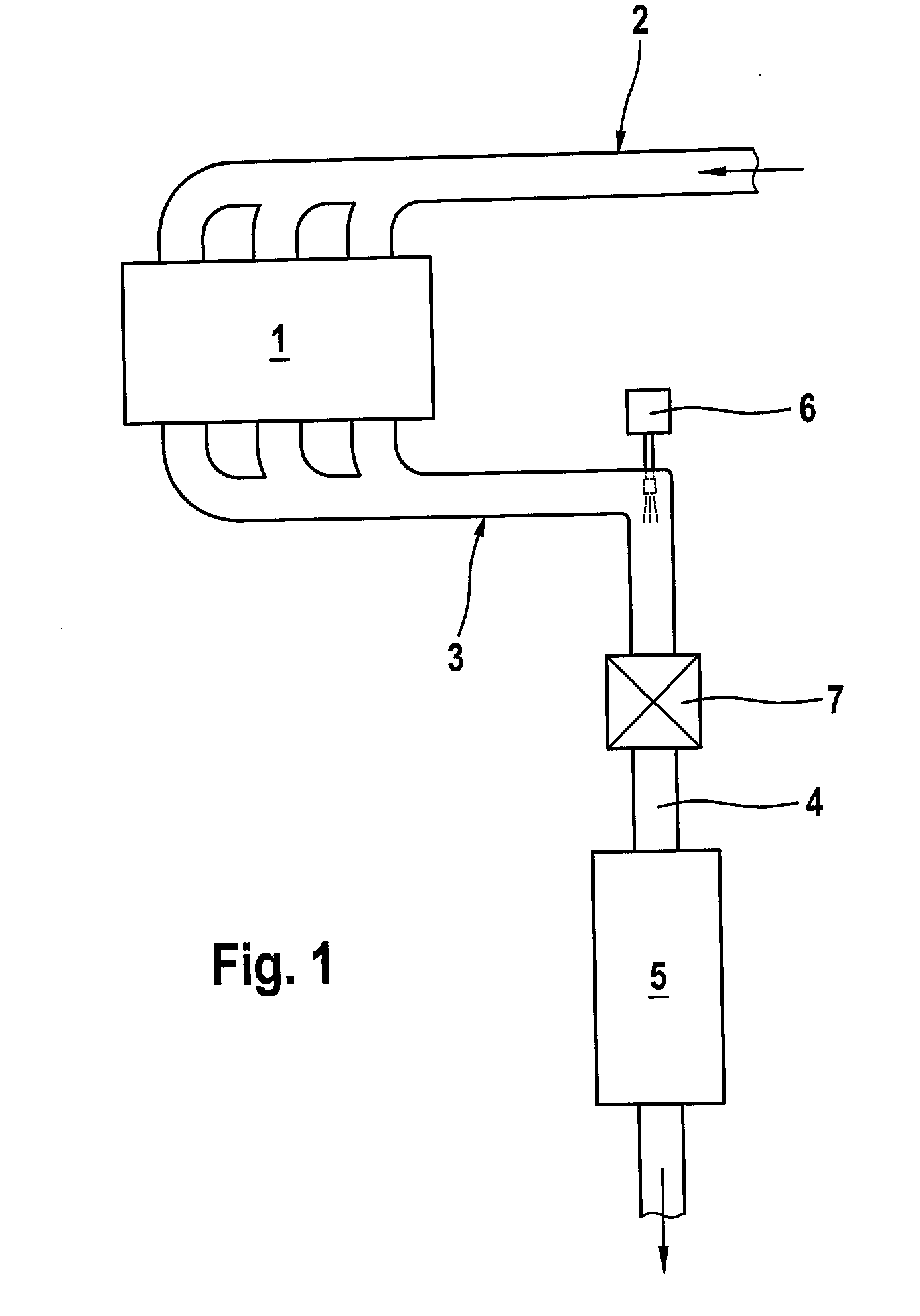
[0011]FIG. 1 shows a greatly simplified basic diagram of an exhaust system,

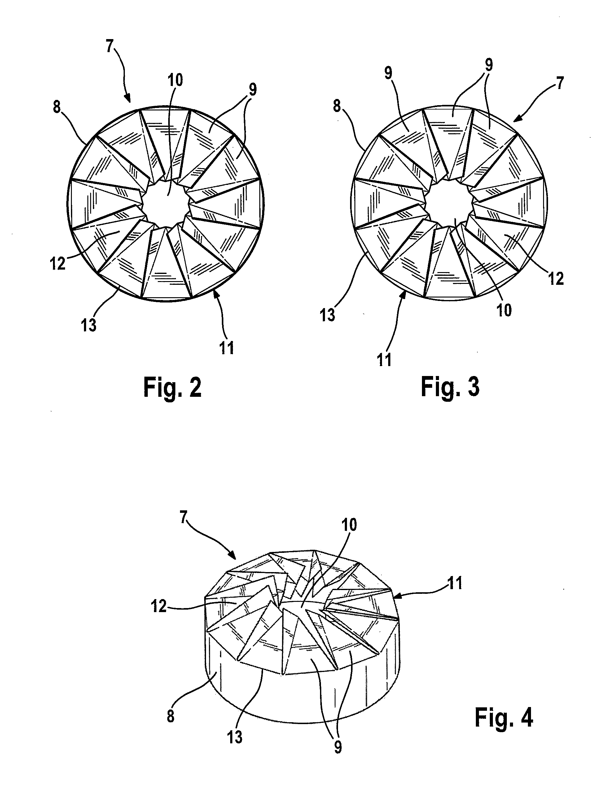
[0012]FIG. 2 shows an axial view of a mixing and / or evaporation installation,

[0013]FIG. 3 shows an axial view like that in FIG. 2, but in the opposite direction of viewing,

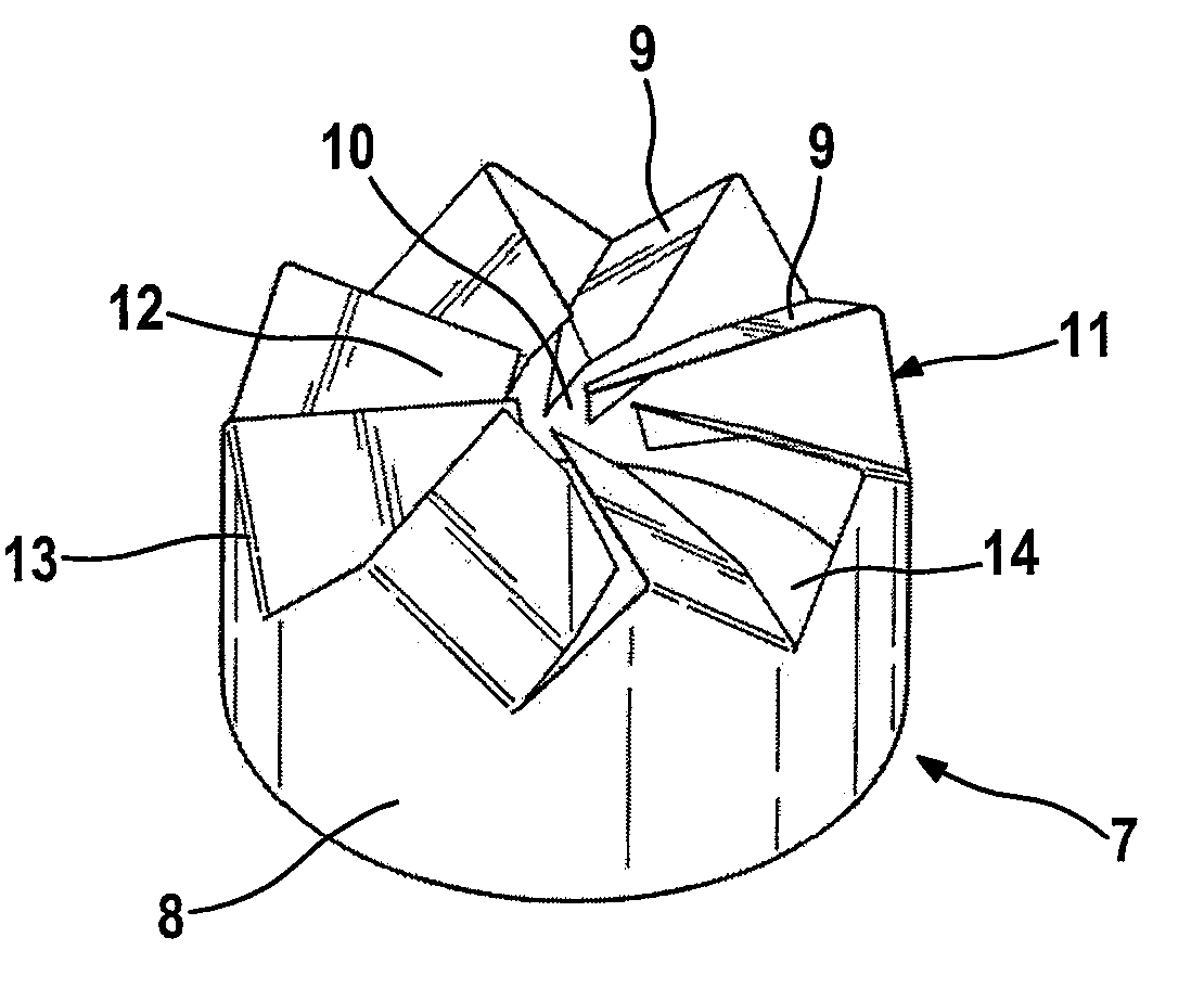
[0014]FIG. 4 shows a perspective view of the mixing and / or evaporation installation shown in FIGS. 2 and 3,

[0015]FIG. 5a shows a view like that in FIG. 2, but of another embodiment,

[0016]FIG. 5b shows a view like that in FIG. 5a, but with a ring area indicated symbolically,

[0017]FIG. 6a shows a view like that in FIG. 3, but in the embodiment according to FIG. 5a,

[0018]FIG. 6b shows a view like that in FIG. 6a, but with a ring area represented symbolically,

[0019]FIG. 7 shows a perspective view of the mixing and / or evaporation installation of FIGS. 5 and 6,

[0020]FIGS. 8a through 8g show views of a sheet metal body in various states as part of the production of a mixing and / or evaporation installation according to ...


PUM

PropertyMeasurementUnit
Angleaaaaaaaaaa
Areaaaaaaaaaaa

Abstract

The invention relates to a mixing and/or evaporation device for an exhaust system, an internal combustion engine, having a tubular body on whose one axial end are arranged several blades adjacent to one another in the circumferential direction, protruding radially inward and leaving free a central passage such that the blades are set at an angle to the axial direction. For inexpensive manufacturing, the tubular body may be manufactured from a single sheet metal body by shaping together with the blades.

Description

CLAIM OF PRIORITY[0001]This application claims foreign priority of German Patent Application No. DE 10 2007 019 878.9, filed Apr. 25, 2007 in Germany, which application is hereby incorporated by reference in its entirety.FIELD OF THE INVENTION[0002]The present invention relates to a mixing and / or evaporation device for an exhaust system of an internal combustion engine. The invention also relates to a method for manufacturing such a mixing and / or evaporation device as well as an exhaust system equipped with such mixing and / or evaporation installation.BACKGROUND OF THE INVENTION[0003]In exhaust systems of internal combustion engines, it may be necessary for various reasons to spray a liquid educt into the exhaust stream. For example, fuel may be injected into the exhaust stream upstream from an oxidation catalyst to trigger an exothermic combustion reaction on a downstream oxidation catalyst. Likewise, a reducing agent such as ammonia, for example, may be sprayed into the exhaust str...

Claims


Application Information

Patent Timeline
IPC IPC(8): F01D5/02B01F23/10
CPCB01F3/022B01F5/0451B01F5/0616Y10T29/49316B01F2005/0639F01N3/206B01F2005/0625Y02A50/20B01F23/12B01F25/3131B01F25/4315B01F25/4316B01F25/431974
Inventor WIRTH, GEORG
Owner PUREM GMBH
Why Eureka
Try Eureka