Sealed Joint Structure for Electrochemical Device

a technology of electrochemical devices and seals, which is applied in the direction of sustainable manufacturing/processing, cell components, climate sustainability, etc., can solve the problems of limited quality and robustness of high-temperature electrochemical devices, and the general recognition of planar designs as significant safety and reliability concerns, etc., to achieve easy manufacturing and improve the effect of joint strength

Active Publication Date: 2008-10-30
RGT UNIV OF CALIFORNIA
View PDF101 Cites 27 Cited by
  • Summary
  • Abstract
  • Description
  • Claims
  • Application Information

AI Technical Summary

Benefits of technology

[0013]An important feature of the invention lies in the partial or complete separation of the various joint functions so that materials and methods appropriate to each function can be combined to produce a joint that fulfills all the functional requirements, while containing all the functional materials in a compact volume. Traditionally, the various functions of the described joint require physical separation of the functional entities. The compact joint described here is expected to be inexpensive and easy to manufacture and to provide for a compact multi-cell structure.
[0014]Some particular

Problems solved by technology

However, planar designs are generally recognized as having significant safety and reliability concerns due to the complexity of sealing of the units and manifolding a planar stack.
The utility of high-temperature (e.g., greater than 800° C., for example between about 900 and 1000° C.) electrochem

Method used


Image

  • Sealed Joint Structure for Electrochemical Device
  • Sealed Joint Structure for Electrochemical Device
  • Sealed Joint Structure for Electrochemical Device

Examples


Embodiment Construction

[0019]Reference will now be made in detail to specific embodiments of the invention. Examples of the specific embodiments are illustrated in the accompanying drawings. While the invention will be described in conjunction with these specific embodiments, it will be understood that it is not intended to limit the invention to such specific embodiments. On the contrary, it is intended to cover alternatives, modifications, and equivalents as may be included within the scope of the appended claims. In the following description, numerous specific details are set forth in order to provide a thorough understanding of the present invention. The present invention may be practiced without some or all of these specific details. In other instances, well known process operations have not been described in detail in order not to unnecessarily obscure the present invention.

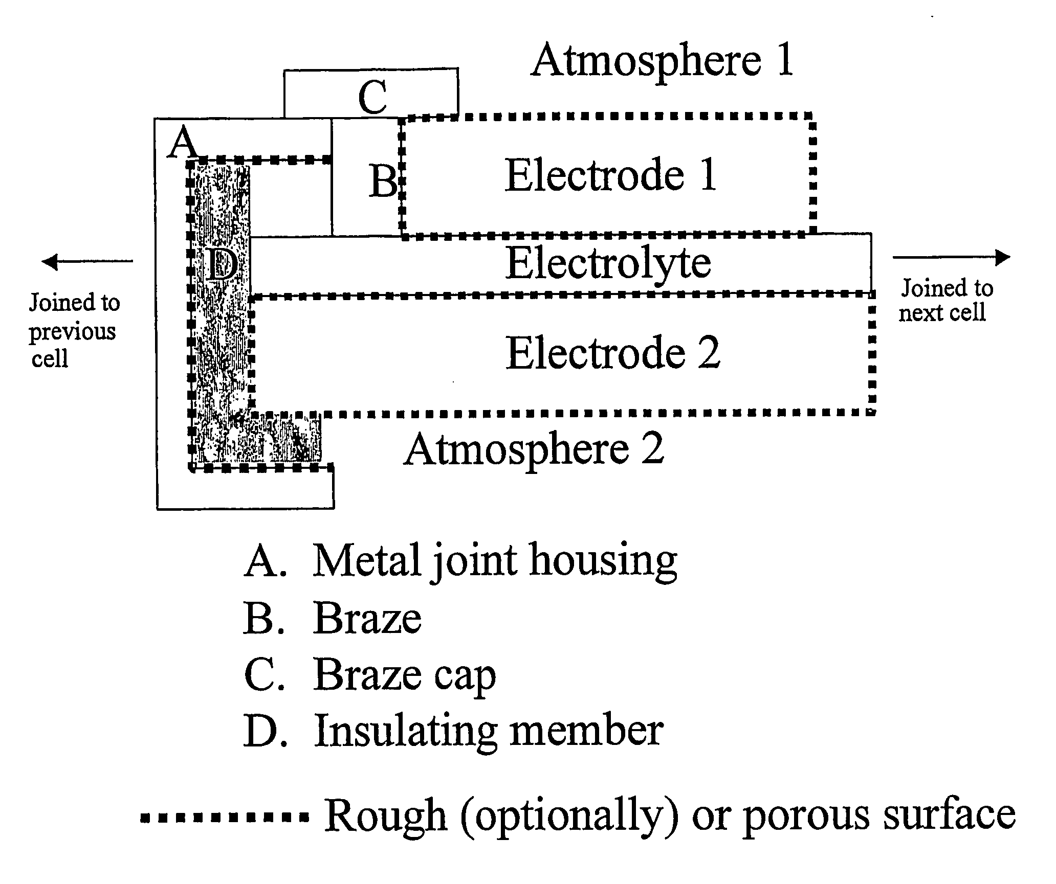
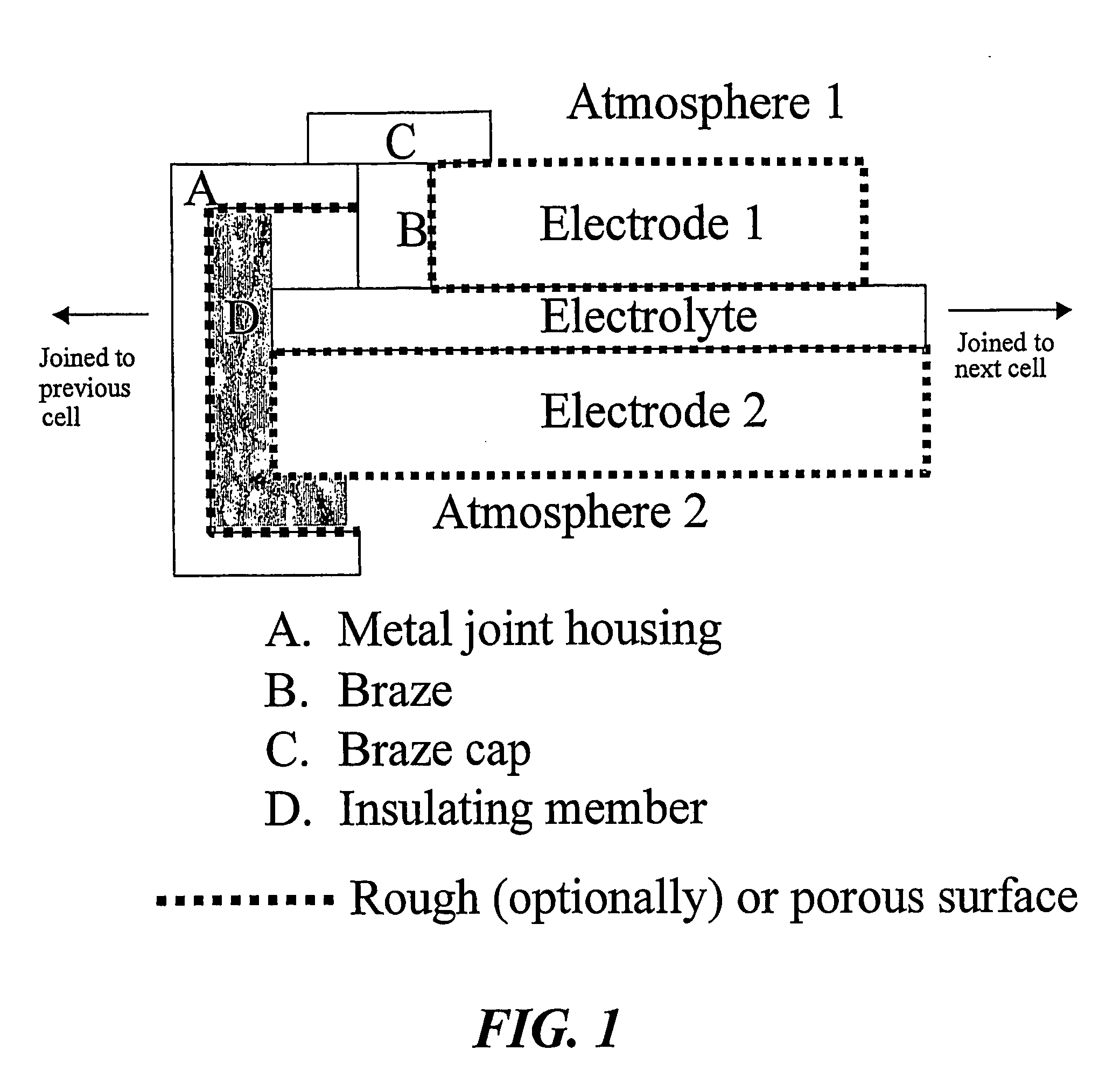
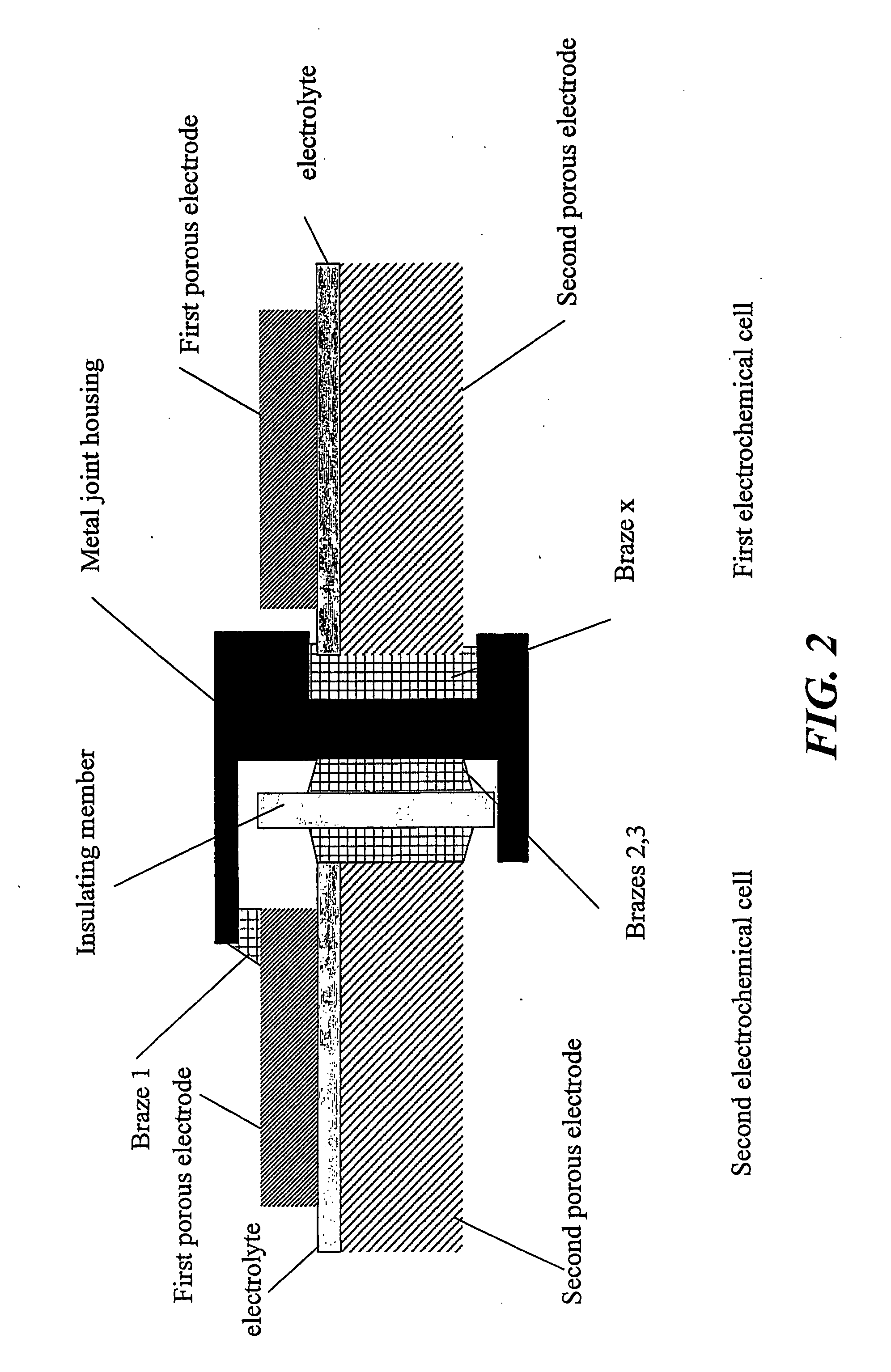
[0020]The invention includes several members making up a joint, wherein the various members perform different functions. The jo...


PUM

PropertyMeasurementUnit
Temperature coefficient of resistanceaaaaaaaaaa
Temperatureaaaaaaaaaa
Coefficient of linear thermal expansionaaaaaaaaaa

Abstract

Several members make up a joint in a high-temperature electrochemical device, wherein the various members perform different functions. The joint is useful for joining multiple cells (generally tubular modules) of an electrochemical device to produce a multi-cell segment-in-series stack for a solid oxide fuel cell, for instance. The joint includes sections that bond the joining members to each other; one or more seal sections that provide gas-tightness, and sections providing electrical connection and/or electrical insulation between the various joining members. A suitable joint configuration for an electrochemical device has a metal joint housing, a first porous electrode, a second porous electrode, separated from the first porous electrode by a solid electrolyte, and an insulating member disposed between the metal joint housing and the electrolyte and second electrode. One or more brazes structurally and electrically connects the first electrode to the metal joint housing and forms a gas tight seal between the first electrode and the second electrode.

Description

CROSS-REFERENCE TO RELATED APPLICATIONS[0001]This application claims priority to U.S. Provisional Patent Application No. 60 / 632,015 filed Nov. 30, 2004, entitled SEALED JOINT STRUCTURE FOR ELECTROCHEMICAL DEVICE. STATEMENT OF GOVERNMENT SUPPORT[0002]This invention was made with government support under Contract DE-AC02-05CH11231 awarded by the United States Department of Energy to The Regents of the University of California for the management and operation of the Lawrence Berkeley National Laboratory. The government has certain rights in this invention.FIELD OF THE INVENTION[0003]The present invention relates to a sealed joint for high-temperature electrochemical devices, such as solid oxide fuel cells, in particular, modular, parallel electrochemical cell-in-series stacks. The joint provides sealing, structural integrity, and electrical connection and insulation.BACKGROUND[0004]Solid-state electrochemical devices are normally cells that include two porous electrodes, the anode and ...

Claims


Application Information

Patent Timeline
IPC IPC(8): H01M2/08H01M50/186H01M50/191
CPCB32B2315/02C04B35/016C04B37/006C04B37/026C04B2235/3213C04B2235/3227Y10T29/4911C04B2237/348H01M2/08H01M8/0271H01M8/243Y02E60/50C04B2237/125Y02P70/50Y02E60/10H01M8/2404H01M50/186H01M50/191
Inventor TUCKER, MICHAEL C.JACOBSON, CRAIG P.DE JONGHE, LUTGARD C.VISCO, STEVEN J.
Owner RGT UNIV OF CALIFORNIA
Why Eureka
Try Eureka