
Device and method for preparing a recess in a bone

a technology for preparing bones and bones, applied in the field of bone preparation recesses or holes, can solve the problems of increasing pain for patients, affecting the healing process, and inconvenient use of single recess screws,

Inactive Publication Date: 2008-10-30
STRYKER EURO OPERATIONS HLDG LLC +1
View PDF26 Cites 39 Cited by
  • Summary
  • Abstract
  • Description
  • Claims
  • Application Information

AI Technical Summary

Benefits of technology

[0005]One aspect of the present invention is to provide a punching device for preparing a recess in a bone, a punching tool adapted to be used in such punching device or an implant adapted to be used as a punching tool for such punching device. A method is also disclosed for preparing a recess in a bone wherein the necessity of preparing a plurality of recesses can be avoided when an implantation device is to be inserted into a bone such that it can accommodate rotational forces between it and the bone.
[0018]According to another embodiment, the punching tool comprise a metallic material. E.g. any kind of stainless steel, titanium alloys, aluminium alloys such as Ti6Al4v, APX, 1.4057, 1.4442, etc can be used. Bio-compatible metals are preferably used. Such bio-compatible material can be used for the punching tool in order to avoid interferences from occurring when punching a recess into a bone.
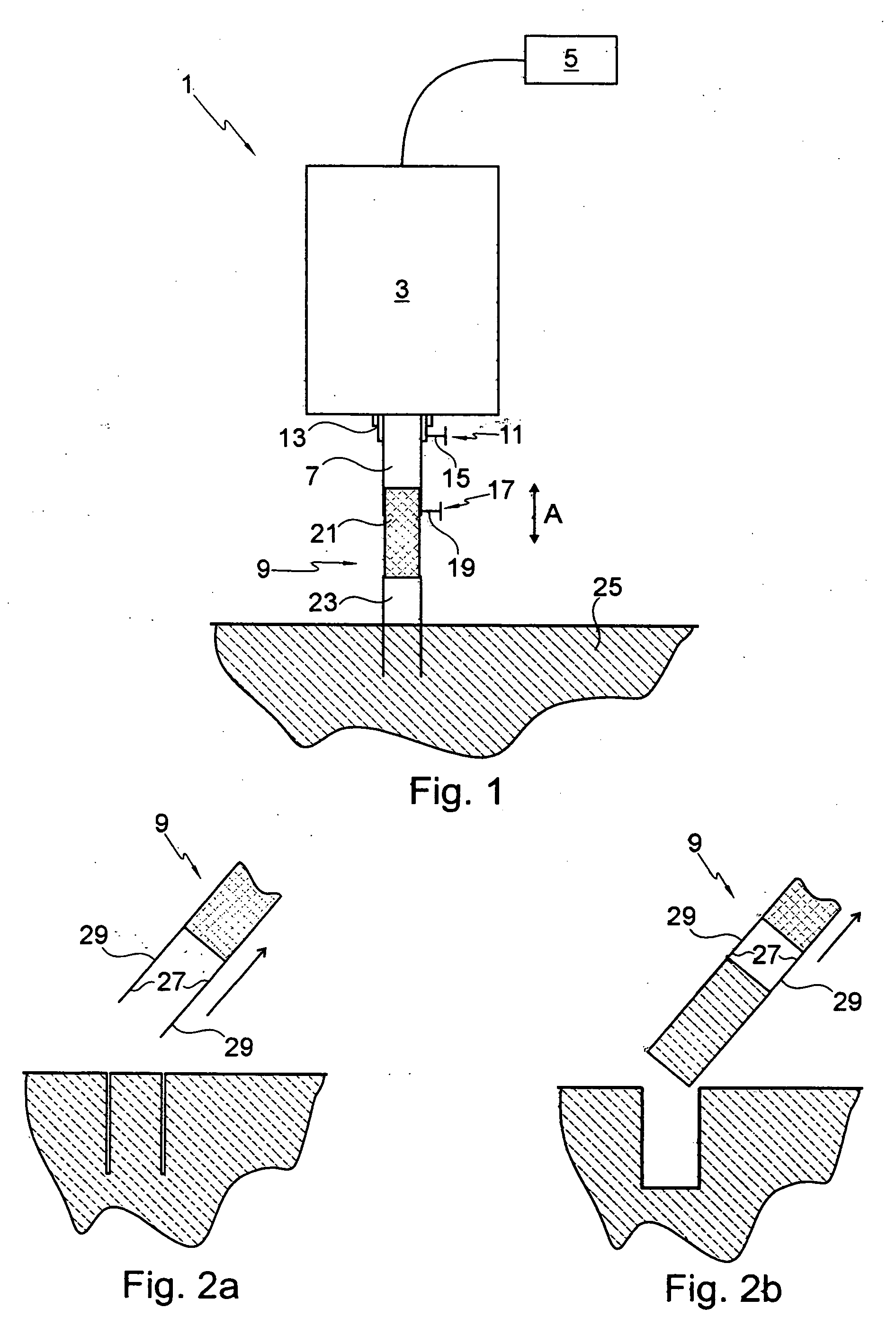
[0020]According to another embodiment, the thin-walled portion of the punching tool has a lateral surface providing a high surface friction. For example, in a thin-walled portion having an annular cross-section it may be advantageous to provide the inner surface of the thin-walled portion such that high surface friction is obtained e.g. by providing this surface with a suitable surface geometry such as for example an increased roughness or by providing this surface with a material having a high coefficient of friction. Using such punching tool the punching tool may be first forced into the bone thereby preparing a recess in the form of the annular cross-section. Subsequently, when withdrawing the punching tool from the bone, the thin-walled portion having such high surface friction on its inner surface may entrain the bone portion located within the annular thin-walled portion, thereby preparing a complete hole comprising both the annular cross-section and the area therein. Accordingly, with such punching device a recess can be prepared in a bone the cross-section of which is substantially larger than the cross-section of the thin-walled portion of the punching tool.
[0023]According to a further embodiment the ultrasonic generator is adapted to excite the punching tool with a vibration amplitude of between 1 μm and 300 μm, preferably between 5 μm and 100 μm. The vibration amplitude is defined in a direction perpendicular to the initial contact surface between the thin-walled portion of the punching tool and the bone, this being usually a longitudinal direction of the punching tool. The vibration amplitude might be selected taking into account the kind of bone into which a recess is to be introduced. For example, in weak bones a small vibration amplitude of e.g. 5 μm might be advantageous in order not to excessively stress such bones whereas in strong bones a higher vibration amplitude of e.g. 100 μm might be advantageous as the recess can be prepared faster.

Problems solved by technology

Due to this circular cross-section, a single recess-screw-combination is not suitable to accommodate rotation forces applied around the axis of the screw.
Furthermore, the preparation of a plurality of recesses in a bone may increase the discomfort for a patient and may delay the healing.

Method used


Image

  • Device and method for preparing a recess in a bone
  • Device and method for preparing a recess in a bone
  • Device and method for preparing a recess in a bone

Examples


Embodiment Construction

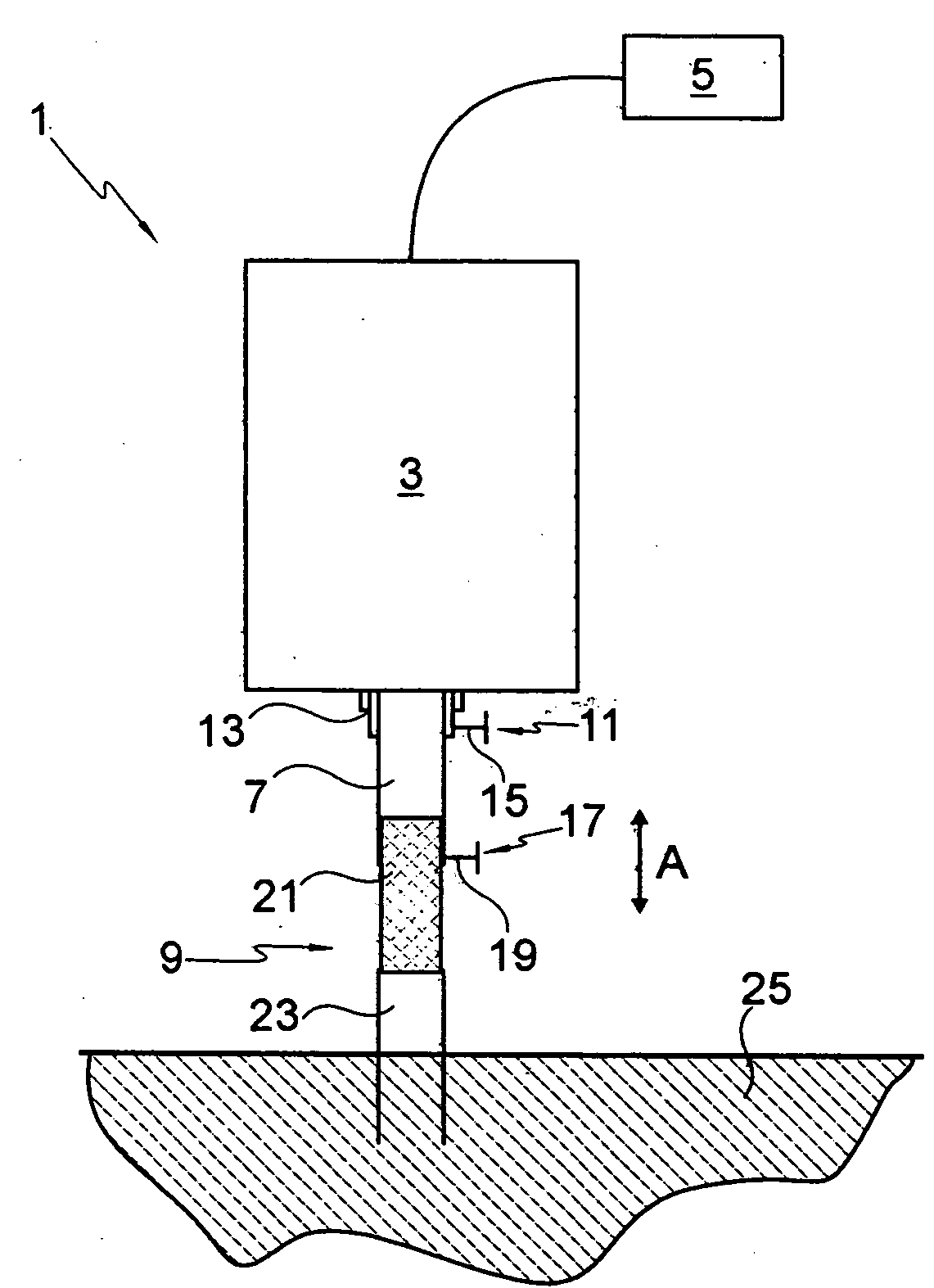
[0037]As schematically shown in FIG. 1, a punching device 1 according to an embodiment of the invention comprises an ultrasonic generator 3 controlled via a control 5, an ultrasonic sonotrode 7 and a punching tool 9.

[0038]The ultrasonic sonotrode 7 is coupled to the ultrasonic generator 3 via a fixation mechanism 11 which can comprise for example a frame 13 and a clamping screw 15. The ultrasonic generator 3 is adapted to emit ultrasonic vibrations with an adaptable frequency of e.g. 20 to 50 kHz which are transmitted to the sonotrode 7. The arrow A in FIG. 1 indicates a direction of these ultrasonic vibrations. Furthermore, the ultrasonic generator 3 may be adapted to produce ultrasonic vibrations with a selectable amplitude of between 5 and 100 μm along the direction A.

[0039]The punching tool 9 is coupled to the ultrasonic sonotrode 7 via a further fixation mechanism 17 which can comprise a clamping screw 19. Thereby, the ultrasonic vibrations can be transmitted from the sonotrode...


PUM


Abstract

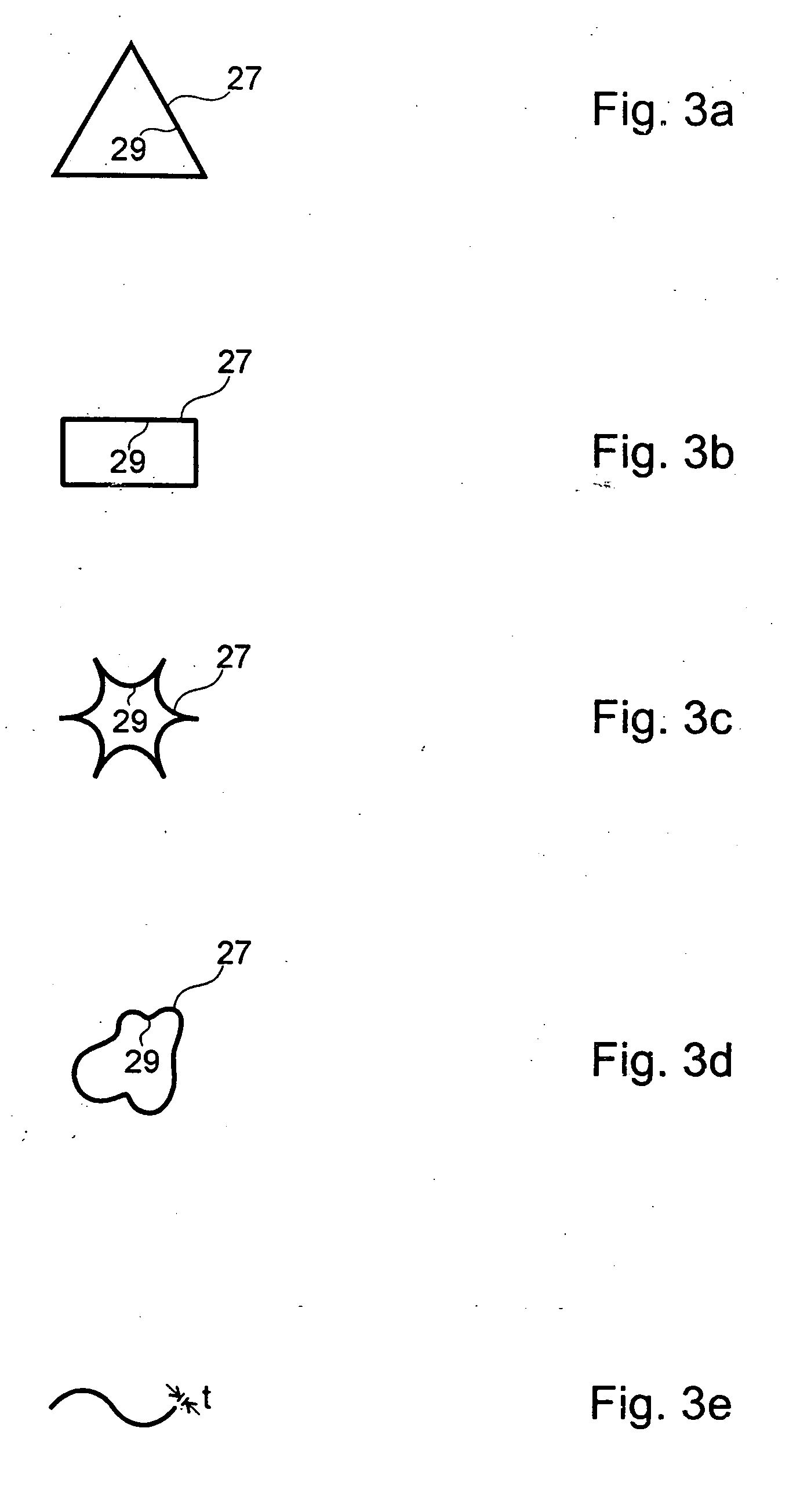
A punching device for preparing a recess in a bone has a punching tool usable for such a punching device. An implant usable with the punching tool is provided and a method for preparing a recess in a bone are disclosed. The punching device comprises an ultrasonic sonotrode and a punching tool which is fixable to the sonotrode at its proximal extremity. At its distal extremity, the punching tool has a thin-walled portion having a non-rotational symmetric cross-section. By ultrasonic vibration of the punching tool, the thin-walled portion can be forced into a bone thereby preparing a recess of which is not rotationally symmetric. Subsequently, an implant can be held in such recess. Due to its lack of rotational symmetry, the implant may absorb rotational forces around its longitudinal axis.

Description

CROSS REFERENCE TO RELATED APPLICATION[0001]This application claims the benefit of the filing date of U.S. Provisional Patent Application No. 60 / 926,884 filed Apr. 30, 2007, the disclosure of which is hereby incorporated herein by reference.BACKGROUND OF THE INVENTION[0002]The invention relates to preparing recesses or holes in bones of humans or animals. In such recesses or holes implants e.g. in the form of screws may be introduced. Such screws may be used for example to treat fractures of bones.[0003]Conventionally, the recesses were generally drilled with a rotating tool and both the recesses and the screws or pins to be inserted therein usually have a circular cross-section. Due to this circular cross-section, a single recess-screw-combination is not suitable to accommodate rotation forces applied around the axis of the screw. In order to accommodate such rotation forces which may occur for example when fixing two parts of bones together or when fixing an implant to a bone, it ...

Claims


Application Information

Patent Timeline
IPC IPC(8): A61H1/00A61B17/14
CPCA61B10/025A61B17/1604A61B17/32053A61B2017/00004A61B2017/00371A61B17/320068A61B17/864A61B17/8894A61B2017/320072
Inventor DORAWA, KLAUS
Owner STRYKER EURO OPERATIONS HLDG LLC
Learn More