
Support structure of heater

a technology for supporting structures and heaters, which is applied in the direction of lighting and heating apparatus, furnace crowns/roofs, furnaces, etc., can solve the problems of unavoidable softening or deformation of the plate itself, shortening the life of the electric heater, and the plate is more easily softened and deformed, so as to achieve not easily soften or deform and high durability

Active Publication Date: 2008-11-06
NGK INSULATORS LTD
View PDF15 Cites 5 Cited by
  • Summary
  • Abstract
  • Description
  • Claims
  • Application Information

AI Technical Summary

Benefits of technology

[0010]In the heater support structure of the present invention, the heating part of the electric heater is mounted and supported on the upper surface of the insulating ceramic support plate laminated on the SiC-based ceramic plate, so that the SiC-based ceramic plate which comes in contact with the atmosphere in the furnace is not eroded with a erosive gas generated from the material to be fired at the high temperature, for example, the alkaline component, the Si component or the like. In addition, the SiC-based ceramic plate is highly strong at the high temperature. In consequence, the whole support plate is not easily softened or deformed.
[0011]Moreover, when in a continuous electric firing furnace to fire an SiC-based material to be fired at a high temperature of 1300° C. or more, recrystallized SiC or sintered SiC having an oxidizing region at 950 to 1100° C., or nitride bonded SiC is arranged at a high temperature in excess of 1200° C. and Si impregnated SiC having a low maximum use temperature is arranged at a low temperature of 1200° C. or less, a continuous electric firing furnace generally having high durability can advantageously be provided.

Problems solved by technology

It is also disclosed that the heating element softens in excess of a temperature of 1300° C., and a heating part of the heater sags downwards, which might cause disconnection.
However, in recent years, a new material such as a functional ceramic or a highly heat-resistant and strong ceramic has been developed, and it becomes necessary to fire the material in an atmosphere controlled at a high temperature of 1500° C. At such a high temperature, even when an alumina-based refractory is used as the support plate to support the electric heater, the plate itself is unavoidably softened or deformed, which is a cause for shortening of life of the electric heater.
Furthermore, in a case where the material to be fired is an SiC-based ceramic containing an alkaline component or an Si component as a volatile component, problems occur that these components volatilized during the firing permeate and diffuse in the support plate of the alumina-based refractory and that the plate is more easily softened and deformed to further shorten the life of the support plate itself.

Method used


Image

  • Support structure of heater
  • Support structure of heater
  • Support structure of heater

Examples


Embodiment Construction

[0019]Next, an embodiment of a heater support structure according to the present invention will be described with reference to FIGS. 1 to 3.

[0020]FIG. 3 shows a sectional view of a main part in a direction crossing, at right angles, a longitudinal direction of a continuous firing furnace to which a heater support structure of the present invention is applied. In the drawing, electric heaters 3 to heat downwards is disposed in an upper part of a passage 2 of a material to be fired which is surrounded by a ceiling refractory 11, a side wall refractory 12 and a floor refractory 13, and electric heaters 5 to heat upwards is disposed in a lower part of the passage.

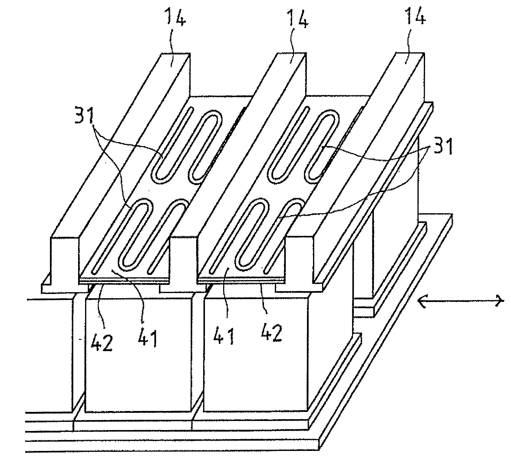
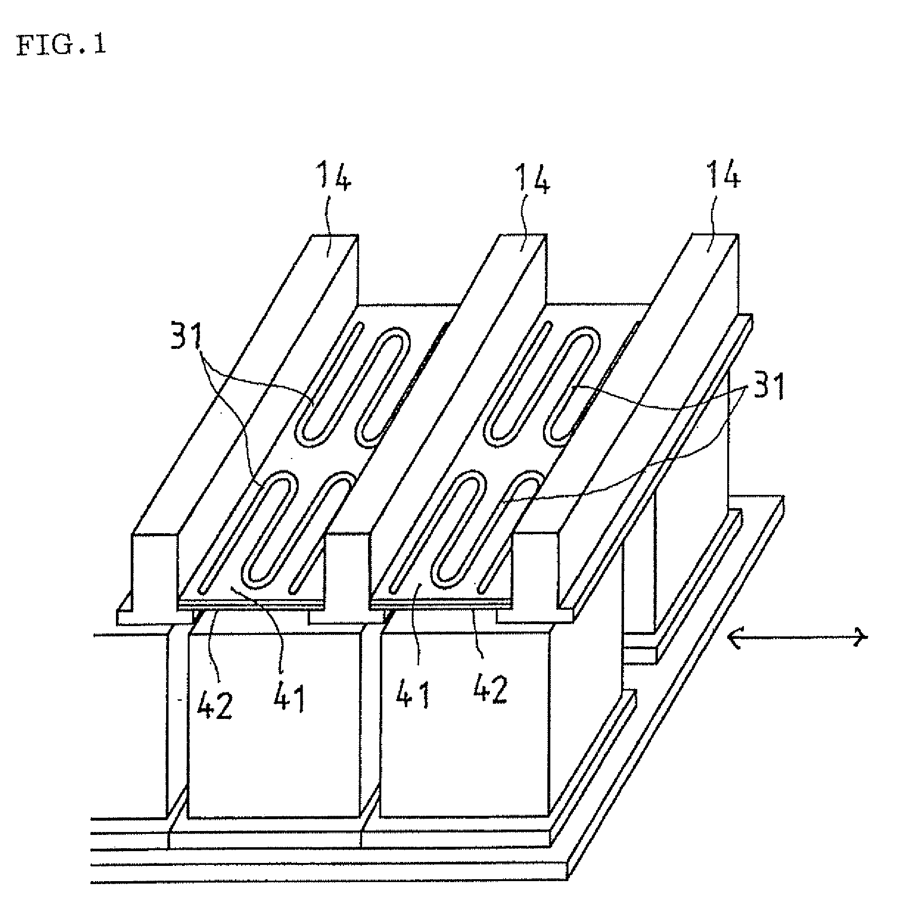
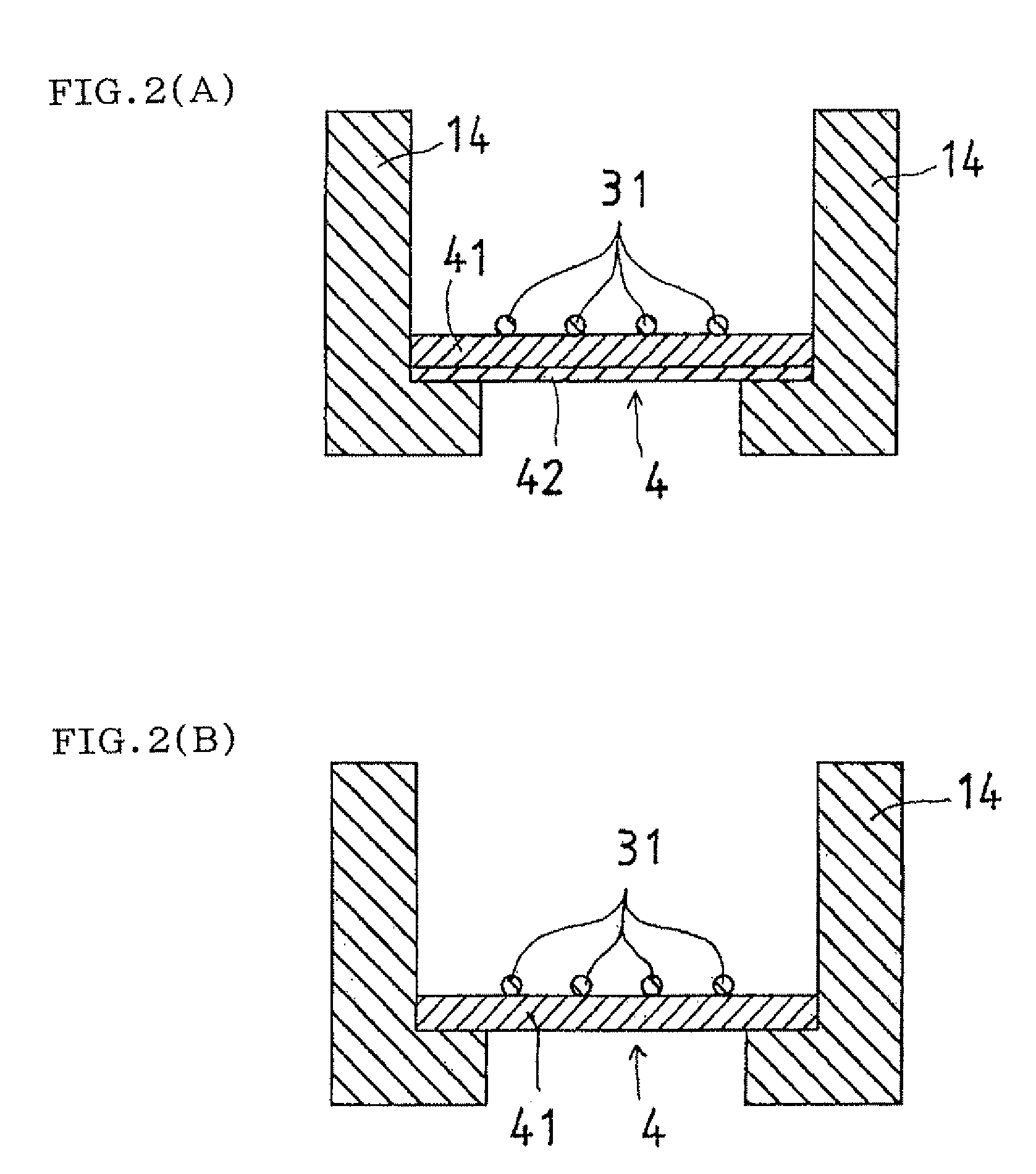
[0021]At least heating parts 31 of the electric heaters 3 arranged in this upper part are mounted and supported on fire-resistant support plates 4, but the present invention is characterized in that as shown in FIGS. 1 and 2A, this support plate 4 has a two-layer structure in which an insulating ceramic support plate 41 is lami...


PUM

PropertyMeasurementUnit
temperatureaaaaaaaaaa

Abstract

There is provided an electric heater support plate which is not likely to be softened or deformed during firing at a high temperature, even if a material to be fired contains an alkaline component or an Si component as a volatile component. A passage 2 for the material to be fired surrounded by a ceiling refractory 11, wall refractories 12 and a floor refractory 13 is provided with an electric heater 3 heating from above and an electric heater 5 heating from below. This electric heater 3 has at least its heating part 31 mounted and supported on a fire-resistant support plate 4, and this support plate 4 in this invention has a two-layer structure in which an insulating ceramic support plate 41 is laminated on an SiC-based ceramic plate 42. The two-layer structure support plates 4 are supported by refractories 14 installed in a furnace and are arranged in parallel in a plurality of rows in a longitudinal direction of the furnace, and the electric heater 3 mounted on the support plates is so constructed as to generate heat by an electric power supplied from an energizing terminal 32 exposed to the outside of a furnace wall.

Description

TECHNICAL FIELD[0001]The present invention relates to the improvement of a support structure of an electric heater for heating which is used in an electric firing furnace. More particularly, it relates to a support structure of a heater of a continuous furnace in which an SiC-based material to be fired can be fired at a high temperature.BACKGROUND ART[0002]Heretofore, a continuous electric firing furnace is disclosed in Patent Document 1 in which an electric heater constituted of an electrically resistant heating element is arranged in the furnace to heat a material to be fired conveyed in the furnace. According to this document, it is disclosed that in a ceiling part of a furnace chamber, an electric heater such as a molybdenum disilicate-based cermet heating element is arranged in a direction crossing a conveyance direction of a treatment target at right angles. It is also disclosed that the heating element softens in excess of a temperature of 1300° C., and a heating part of the ...

Claims


Application Information

Patent Timeline
Patent Type & Authority Applications(United States)
IPC IPC(8): H05B3/06
CPCC04B35/117C04B35/565C04B35/573C04B2235/3463C04B2235/3886C04B2235/80F27B9/36F27D1/02F27D5/0006F27D11/02F27D99/0006F27D11/00
Inventor MIYATA, JOTAROGOSHIMA, TAKASHIIHARA, CHIKASHI
Owner NGK INSULATORS LTD
Learn More