
LC voltage controlled oscillator with tunable capacitance unit

a voltage control and capacitance unit technology, applied in the field of voltage control oscillators, can solve the problem of not providing a tunable kvco, and achieve the effect of avoiding the degradation of out-of-band phase noise due to high kvco

Inactive Publication Date: 2008-11-06
MEDIATEK INC
View PDF3 Cites 26 Cited by
  • Summary
  • Abstract
  • Description
  • Claims
  • Application Information

AI Technical Summary

Benefits of technology

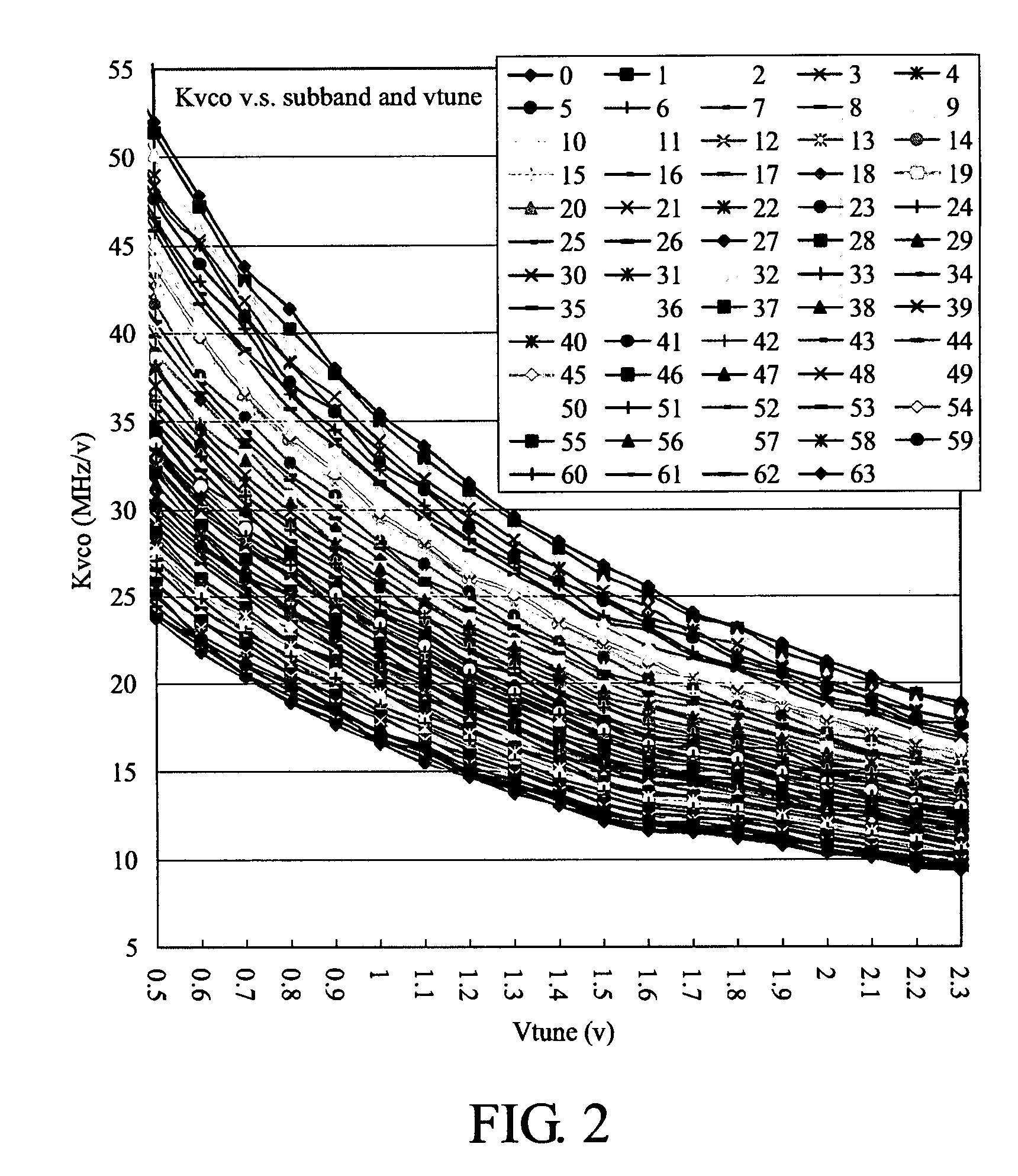
[0009]A LC voltage controlled oscillator (VCO) with a tunable capacitance unit is disclosed. The disclosed LC VCO has a constant gain (KVCO) within a wide frequency band a bandwidth of a phase locked loop (PLL) circuit can be tuned by tuning a gain KVCO of the LC VCO. In addition, requirements for a compensation current of a charge pump circuit in the PLL circuit are relaxed and degradation of out-of-band phase noise due to high KVCO can also be avoided.

Problems solved by technology

However, such arrangement cannot provide a tunable KVCO according to an oscillating frequency of an LC oscillator.

Method used


Image

  • LC voltage controlled oscillator with tunable capacitance unit
  • LC voltage controlled oscillator with tunable capacitance unit
  • LC voltage controlled oscillator with tunable capacitance unit

Examples


Embodiment Construction

[0026]The following description is of the best-contemplated mode of carrying out the invention. This description is made for the purpose of illustrating the general principles of the invention and should not be taken in a limiting sense. The scope of the invention is best determined by reference to the appended claims.

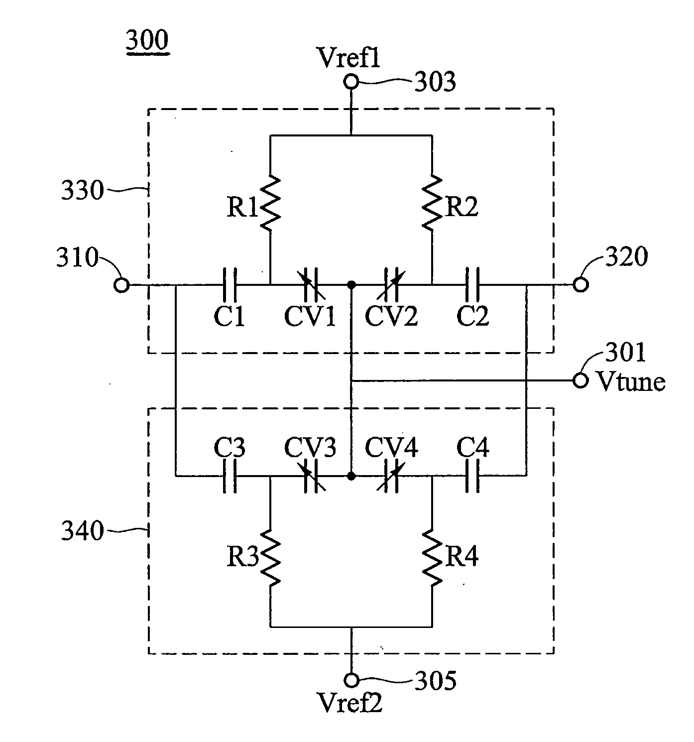
[0027]FIG. 4 is a circuit diagram of a tunable capacitance unit according to an embodiment of the invention. The tunable capacitance unit 300 comprises a tuning input 301 and first and second tuning capacitance units 330 and 340. The first tuning capacitance comprises a first pair of accumulation-mode MOS varactors CV1 / CV2, a first pair of blocking capacitors C1 / C2, and a first pair of biasing resistors R1 / R2. The second tuning capacitance comprises a second pair of accumulation-mode MOS varactors CV3 / CV4, a second pair of blocking capacitors C3 / C4, and a second pair of biasing resistors R3 / R4. A symbol, a schematic and a cross section of the accumulation-mode MOS vara...


PUM


Abstract

A tunable capacitance unit coupled between a pair of circuit nodes. The tunable capacitance unit comprises a tuning input supplying a tuning voltage, and first and second tuning capacitance units. Each of the tuning capacitance units comprises a pair of accumulation-mode MOS varactors with source / drains thereof coupled to the tuning input, a pair of blocking capacitors coupled to a respective gate of the accumulation-mode MOS varactors and to a respective one of the circuit nodes, and a pair of biasing resistors coupled to a respective gate of the accumulation-mode MOS varactors and to a respective bias terminal receiving a respective reference voltage. The reference voltages received by the first and second tuning capacitance units are symmetrical to a predetermined voltage.

Description

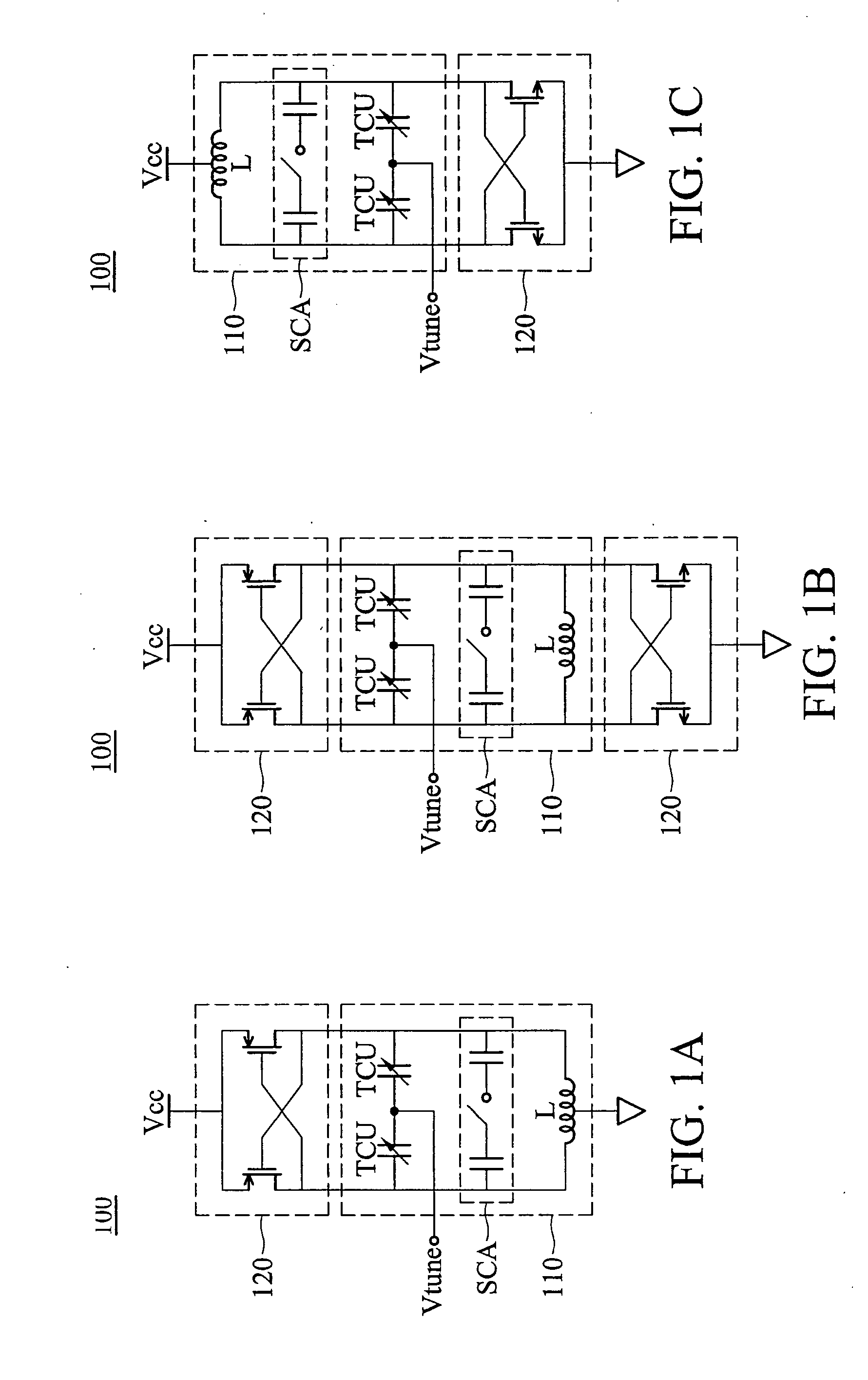
BACKGROUND OF THE INVENTION[0001]1. Field of the Invention[0002]The invention relates to a voltage controlled oscillator (VCO) and, in particular, to an LC VCO with a tunable capacitance unit.[0003]2. Description of the Related Art[0004]FIGS. 1A, 1B and 1C are respectively a circuit diagram of a LC tank voltage controlled oscillator (VCO) 100, or an LC VCO. The LC VCO 100 typically comprises an LC tank circuit 110 and a negative resistance circuit 120. The LC tank circuit 110 comprises an inductor L and a tunable capacitance unit TCU. A capacitance of the tunable capacitance unit TCU is typically tuned by a tuning voltage Vtune. The negative resistance circuit 120 comprises a pair of MOS transistors, each having a gate, a source and a drain. The gates of the MOS transistors are cross-coupled to the drains thereof and sources thereof are coupled to a fixed voltage, Vcc or ground. In addition, the LC tank circuit 110 further comprises a switch capacitor array SCA such that the LC VCO ...

Claims


Application Information

Patent Timeline
Patent Type & Authority Applications(United States)
IPC IPC(8): H03J3/20H03B7/02H03B7/06H03J3/04
CPCH03B5/1228H03B5/1212H03B5/1265H03B5/124H03B5/1293
Inventor LIN, TSER-YUKE, LING-WEIYU, TAI-YUAN
Owner MEDIATEK INC
Learn More