Gain compensation circuit
- Summary
- Abstract
- Description
- Claims
- Application Information
AI Technical Summary
Benefits of technology
Problems solved by technology
Method used
Image
Examples
Embodiment Construction
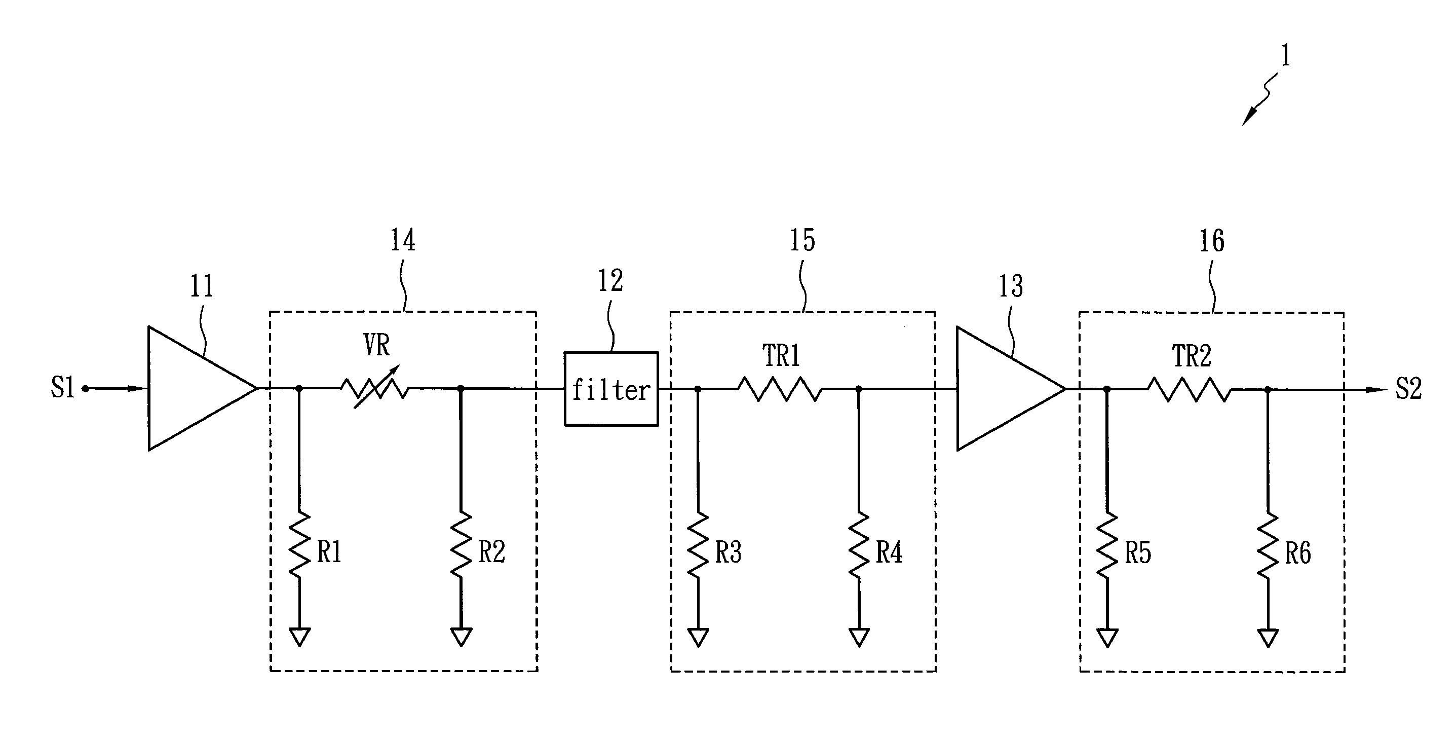
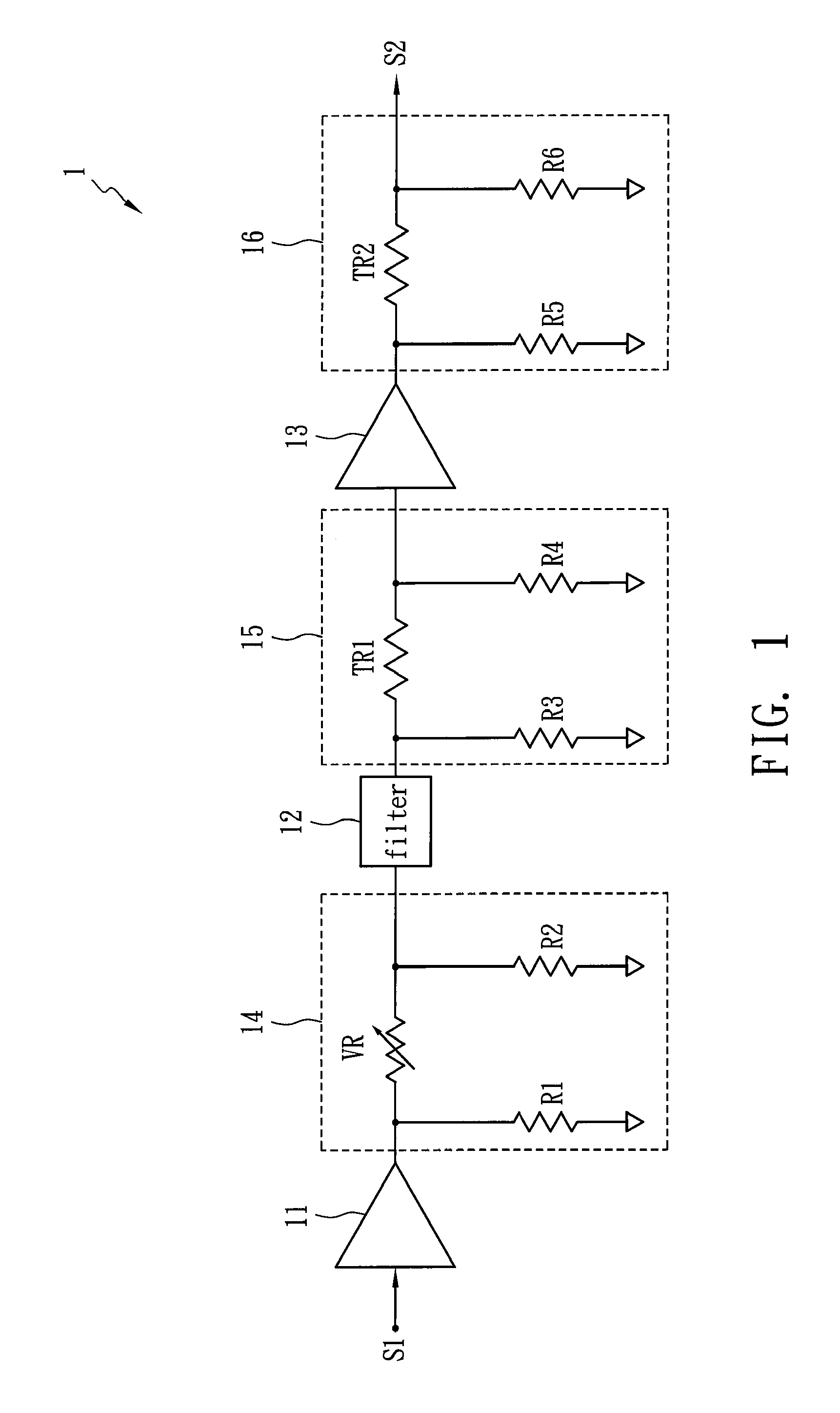
[0014]FIG. 1 shows a hint diagram of a gain compensation circuit 1 in accordance with one embodiment of the present invention. The gain compensation circuit 1 is applied to a microwave transceiver and includes a first amplifier 11, a gain adjuster 14, a filter 12, first attenuator 15, a second amplifier 13 and a second attenuator 16. The gain adjuster 14 is disposed between the first amplifier 11 and the filter 12 so as to adjust a nominal gain of a manufactured microwave transceiver at a normal temperature (about 25° C.) by means of a variable resistor VR. Accordingly, mass-production microwave transceivers each have the same nominal gain, and the variation of the gain relating to temperature remains the same as well. The first attenuator 15 is disposed between the filter 12 and the second amplifier 13 for providing a first gain compensation, which has a small compensation range and is used to reduce the degradation of noise figure. The second attenuator 16 is used to provide a sec...
PUM
 Abstract
Description
Claims
Application Information
 - R&D
- Intellectual Property
- Life Sciences
- Materials
- Tech Scout
- Unparalleled Data Quality
- Higher Quality Content
- 60% Fewer Hallucinations
Browse by: Latest US Patents, China's latest patents, Technical Efficacy Thesaurus, Application Domain, Technology Topic, Popular Technical Reports.
© 2025 PatSnap. All rights reserved.Legal|Privacy policy|Modern Slavery Act Transparency Statement|Sitemap|About US| Contact US: help@patsnap.com


