Rotary clock flash analog to digital converter system and method
What is Al technical title?
Al technical title is built by PatSnap Al team. It summarizes the technical point description of the patent document.
a converter and rotary clock technology, applied in transmission systems, automatic control, instruments, etc., can solve the problems of inability to counter and use too much power, and achieve the effects of low impedance time reference, low aperture jitter in sampling circuitry, and less sensitive to process thresholds
Active Publication Date: 2008-11-06
ANALOG DEVICES INC
View PDF43 Cites 48 Cited by
Summary
Abstract
Description
Claims
Application Information
AI Technical Summary
This helps you quickly interpret patents by identifying the three key elements:
Problems solved by technology
Method used
Benefits of technology
Problems solved by technology
Obviously, such a counter is not feasible at this time and even if such a counter could be constructed, it would use too much power.
Method used
Image
Click on the blue label to locate the original text in one second.
Reading with bidirectional positioning of images and text.
Examples
Embodiment Construction
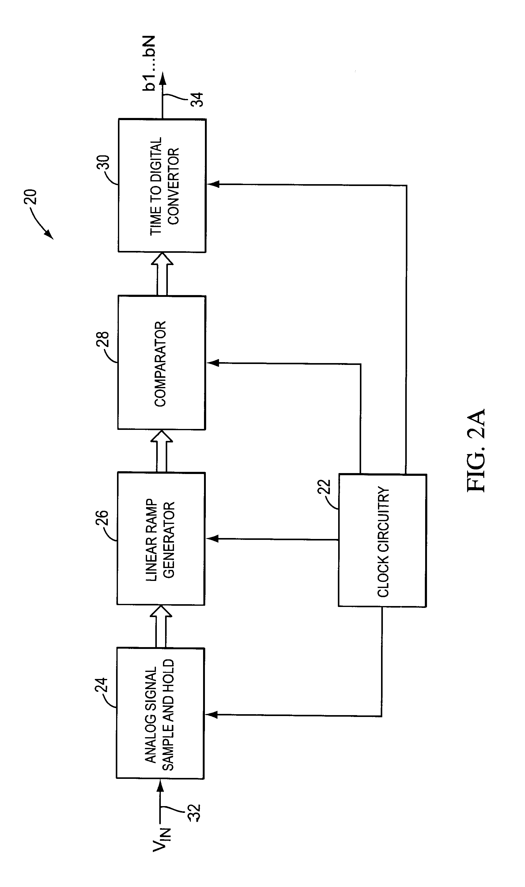
[0053]FIG. 2A shows an embodiment 20 in block diagram form the ADC of the present invention. The embodiment includes a clock circuitry block 22, an analog signal sample and hold unit 24, a linear ramp generator 26, a comparator 28, and a time-to-digital converter (TDC) 30. The analog sample and hold unit 24 receives the signal to be converted VIN 32 and captures the signal during a precisely controlled time interval. The linear ramp generator 26 generates a ramp starting at a particular input voltage. The comparator 28 compares the voltage output of the linear ramp generator 26 against a reference voltage (or a threshold voltage) and the time-to-digital converter 30, converts a time pulse into a digital number 34, which may be coded.
[0054]FIG. 2B shows a simplified timing diagram 40 for describing the operation of the block diagram 20 in FIG. 2A. There are two time periods, tSAMPLE 42 and tCONVERT 44 (although in more complex embodiments, there may be additional time intervals). Dur...
PUM
Abstract
System and method for converting an analog voltage to a digital signal. The system includes an input voltage sampler, a ramp generator, a comparator, a time-to-digital converter (TDC), and a multiphase oscillator, preferably a rotary traveling wave oscillator, that provides the critical system timing. The phases of the multiphase oscillator define a sampling interval during which the input voltage is sampled and held and a conversion interval during which the ramp generator, comparator, and TDC operate to convert the sampled voltage to the digital signal. The TDC samples at times provided by the phases of the multiphase oscillator to form the bits of the digital signal. The sampler, ramp generator, and comparator can be constructed from multiple fragments, one of which is selectable for calibration while the rest of the fragments are joined for normal operation. Multiple converters can be interleaved to increase the sampling rate.
Description
CROSS-REFERENCE TO RELATED APPLICATIONS[0001]This application is a continuation of and claims the benefit of U.S. patent application Ser. No. 11 / 616,263, filed Dec. 26, 2006, titled “ROTARY CLOCK FLASH ANALOG TO DIGITAL CONVERTER SYSTEM AND METHOD,” which claims priority to two U.S. Provisional Applications, Ser. Nos. 60 / 754,224, filed Dec. 27, 2005, and titled “ROTARY CLOCK FLASH ANALOG TO DIGITAL CONVERTER SYSTEM AND METHOD,” and 60 / 754,778, filed Dec. 28, 2005, and titled “ROTARY CLOCK FLASH ANALOG TO DIGITAL CONVERTER SYSTEM AND METHOD.”[0002]This application is related to U.S. application Ser. No. 11 / 191,231, filed Jul. 26, 2005, and titled “ROTARY FLASH ADC,” which is incorporated by reference into the present application.[0003]This application incorporates provisional U.S. Application 60 / 716,552, titled “SERIALIZER DESERIALIZER,” Filed Sep. 12, 2005, Attorney Docket No. 374321-02700 (359321) into the present application.FIELD OF THE INVENTION[0004]The present invention relate...
Claims
Application Information
Patent Timeline
Application Date:The date an application was filed.
Publication Date:The date a patent or application was officially published.
First Publication Date:The earliest publication date of a patent with the same application number.
Issue Date:Publication date of the patent grant document.
PCT Entry Date:The Entry date of PCT National Phase.
Estimated Expiry Date:The statutory expiry date of a patent right according to the Patent Law, and it is the longest term of protection that the patent right can achieve without the termination of the patent right due to other reasons(Term extension factor has been taken into account ).
Invalid Date:Actual expiry date is based on effective date or publication date of legal transaction data of invalid patent.
Patent Type & Authority Applications(United States)