Non contact wheel alignment sensor and method

Active Publication Date: 2008-11-06
VERHAERT NEW PROD & SERVICES +1
View PDF58 Cites 38 Cited by
  • Summary
  • Abstract
  • Description
  • Claims
  • Application Information

AI Technical Summary

Benefits of technology

[0006]Accordingly, the present invention provides an apparatus and method for determining the orientation of a three-dimensional object and, which in the preferred form is a tire and wheel assembly for which alignment characteristics are desired. The sensors project multiple light beams at a tire and wheel assembly to form multiple generally p

Problems solved by technology

Direct measurement methods require human operators or mechanisms to place measurement tools in contact with the vehicle and are subject to placemen

Method used


Image

  • Non contact wheel alignment sensor and method
  • Non contact wheel alignment sensor and method
  • Non contact wheel alignment sensor and method

Examples


Embodiment Construction

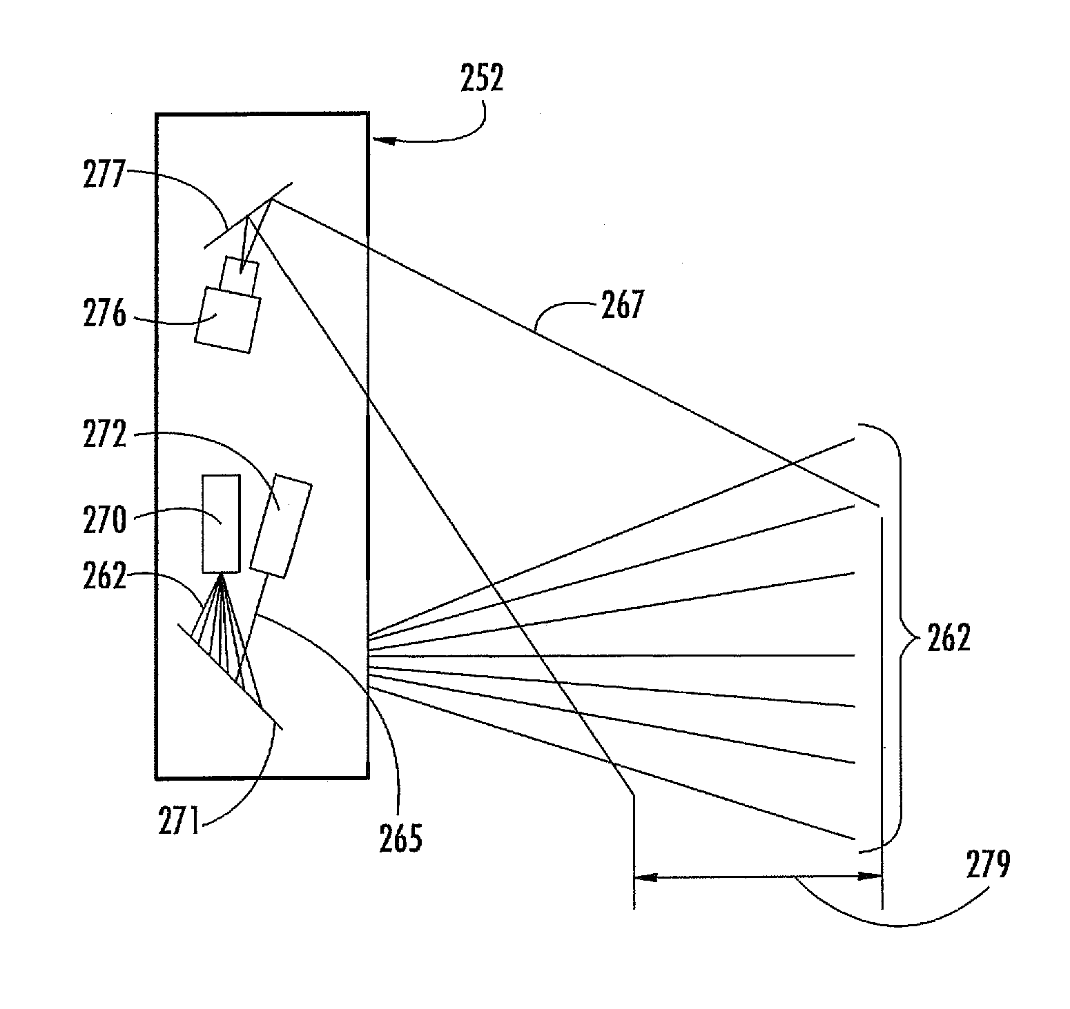
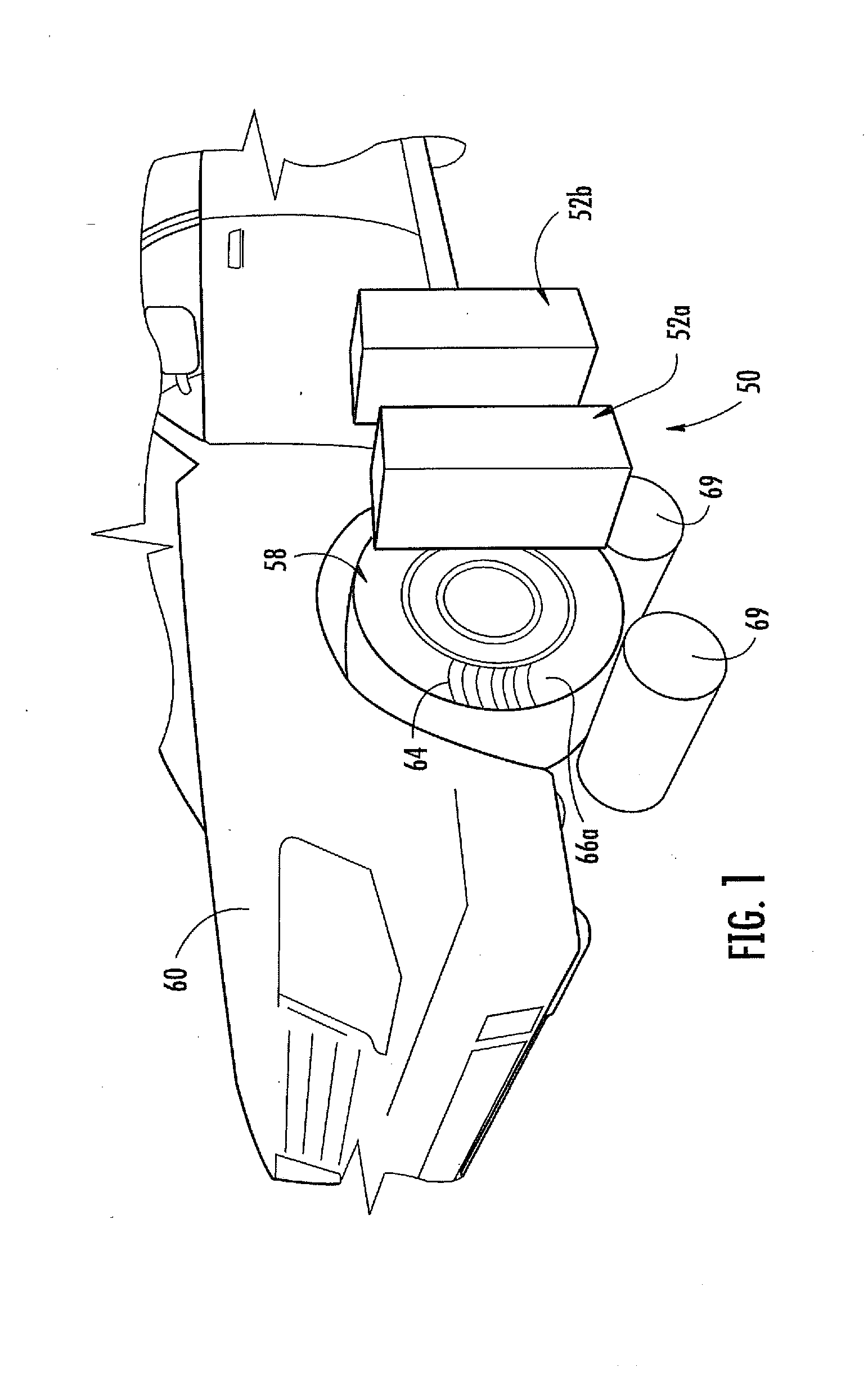
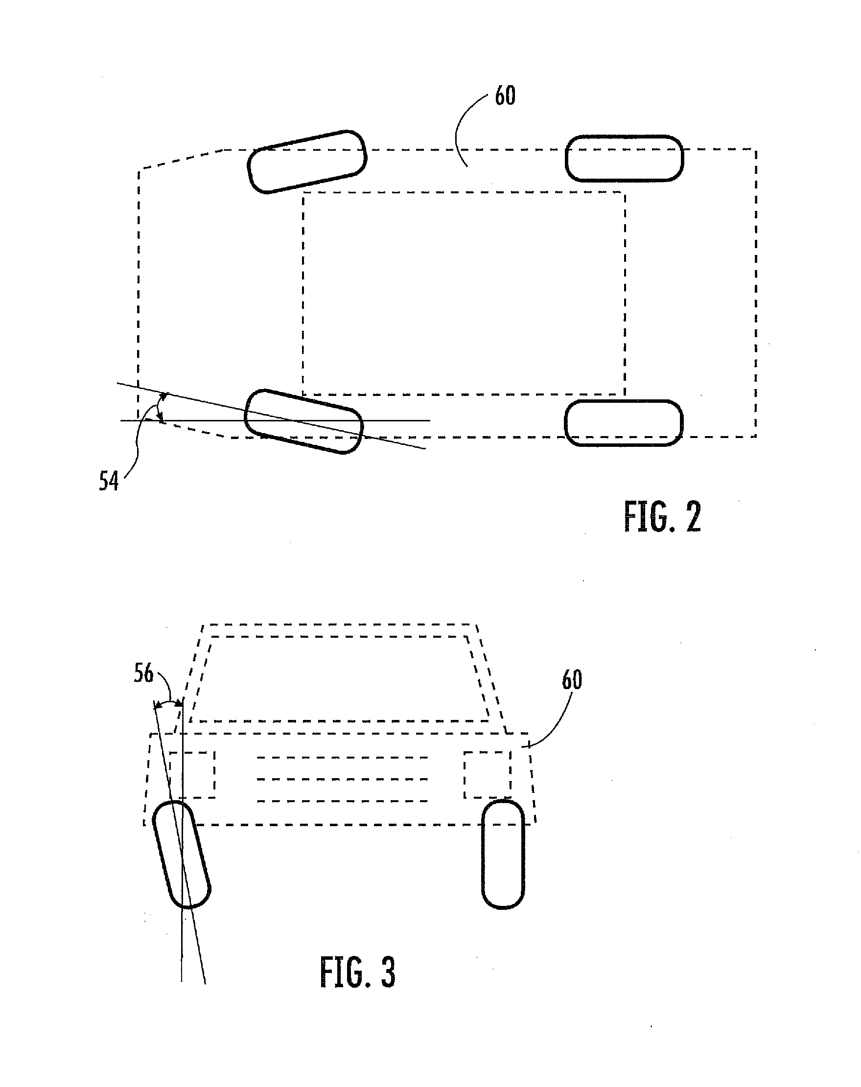
[0038]The present invention will now be described with reference to the accompanying figures, wherein the numbered elements in the following written description correspond to like-numbered elements in the figures. A measurement system or apparatus 50, which in the illustrated embodiment of FIG. 1, comprises a pair of non-contact wheel alignment sensors 52a, 52b is used for determining wheel alignment characteristics such as toe, camber, caster, steering axis inclination (SAI), as well as the wheel center, axis of symmetry, and rear thrust angle. FIG. 2 illustrates the toe angle 54 to be determined and FIG. 3 illustrates the camber angle 56 to be determined. Although only one tire and wheel assembly 50 is illustrated in FIG. 1, it should be understood that a measurement system comprising two sensors 52a, 52b may be placed at either of the front or rear tire and wheel assemblies or at each of the four tire and wheel assemblies of vehicle 60. Alternatively, a single sensor 52 may be us...


PUM


Abstract

A sensor and method of determining the orientation of an object, such as the alignment characteristics of a tire and wheel assembly mounted on a vehicle, includes projecting a plurality of light planes from a first light projector onto a tire and wheel assembly to form a plurality of generally parallel illumination lines on a tire of the tire and wheel assembly, receiving a reflected image of at least some of the illumination lines with a photo electric device reflected from the tire at an angle relative to a projecting angle of the first light projector, and determining a plane defined by spatial coordinates from a selected point located on each illumination line imaged by the photo electric device, with the plane representing the orientation of the tire and wheel assembly.

Description

CROSS REFERENCE TO RELATED APPLICATION[0001]The present application claims priority of U.S. provisional application Ser. No. 60 / 916,004 filed May 4, 2007, by De Sloovere et al. for NON CONTACT WHEEL ALIGNMENT SENSOR, which is hereby incorporated herein by reference in its entirety.FIELD OF THE INVENTION[0002]This invention relates to a measurement apparatus for determining the orientation of a three-dimensional object with respect to a reference system, and more particularly, to a measurement system comprising one or more sensors especially adapted for use with vehicle wheels using light beams projected onto a tire and wheel assembly to define a plane of orientation of the wheel with respect to a predetermined orientation.BACKGROUND OF THE INVENTION[0003]In the automotive industry, proper vehicle quality requires measurement and adjustment of wheel alignment settings, both during manufacture and subsequently during the useful life of the vehicle. Proper positioning and alignment of ...

Claims


Application Information

Patent Timeline
IPC IPC(8): G01B11/275
CPCG01B11/25G01B11/2755G01B2210/286G06T7/0057G06T7/521G01M17/013G01M17/007G01C1/00G01B11/26
Inventor DE SLOOVERE, KRISBEGHUIN, DIDIERVERHAERT, KOEN
Owner VERHAERT NEW PROD & SERVICES
Why Eureka
Try Eureka