Antenna mapping in a MIMO wireless communication system

a wireless communication system and antenna mapping technology, applied in the direction of channel coding adaptation, code conversion, code conversion, etc., can solve the problems of small changes in differential propagation delay, large changes in individual wave phases, and the scheme cannot be applied to two transmission antennas. achieve the effect of improving transmission diversity performance, improving transmission performance, and increasing system throughpu

Inactive Publication Date: 2008-11-06
SAMSUNG ELECTRONICS CO LTD
View PDF12 Cites 90 Cited by
  • Summary
  • Abstract
  • Description
  • Claims
  • Application Information

AI Technical Summary

Benefits of technology

[0015]It is another object to provide an improve method and an improved apparatus for transmitting information in order to improve the transmission performance and increase the system throughput.
[0016]It is another object to provide an improve method and an improved apparatus for transmitting information in order to improve the transmission diversity performance.

Problems solved by technology

The radio wave which arrives at the antenna of the mobile station in a downlink direction, or at the antenna of the base station in an uplink direction, experiences constructive and destructive additions because of different phases of individual waves generated due to the reflections, diffractions, scattering and out-of-phase recombination.
This is due to the fact that, at high carrier frequencies typically used in a contemporary cellular wireless communication, small changes in differential propagation delays introduces large changes in the phases of the individual waves.
One limitation of Alamouti 2×1 space-time diversity scheme is that this scheme can only be applied to two transmission antennas.
The problem with combined SFBC+FSTD scheme and STBC+TSTD schemes is that only a fraction of the total transmission antennas and hence power amplifier capability is used for transmission in a given frequency or time resource.
When the transmit power on the non-zero elements in the matrix is increased, bursty interference is generated to the neighboring cells degrading system performance.
Generally, bursty interference manifests itself when certain phases of a frequency hopping pattern incur more interference than other phases.
Because smaller correlation among antennas means higher achievable diversity, this kind of antenna arrangement may result in degraded transmit diversity performance for the symbols transmitted via the first and the second antennas, and for the symbols transmitted via the third and the fourth antennas.

Method used


Image

  • Antenna mapping in a MIMO wireless communication system
  • Antenna mapping in a MIMO wireless communication system
  • Antenna mapping in a MIMO wireless communication system

Examples


first embodiment

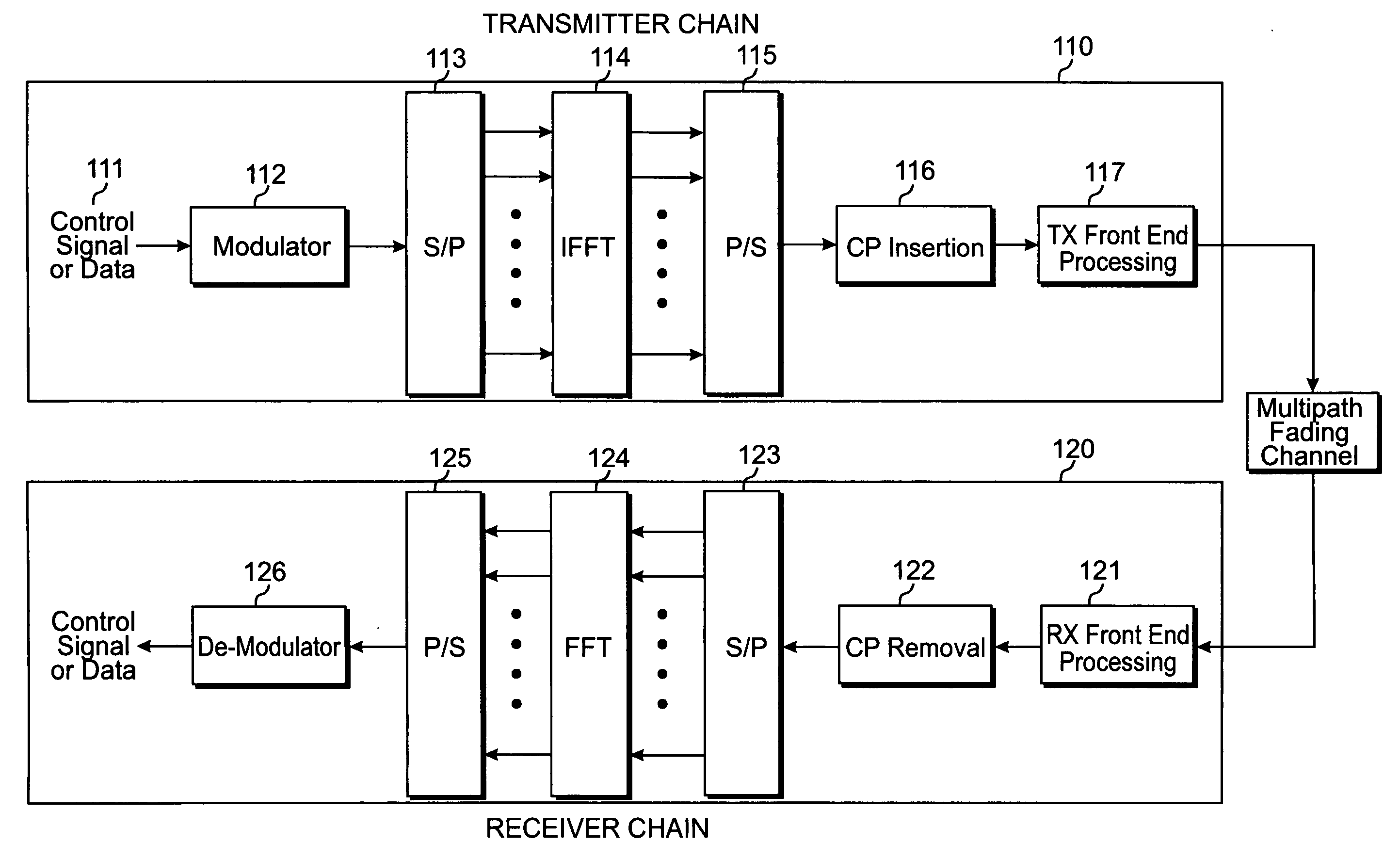
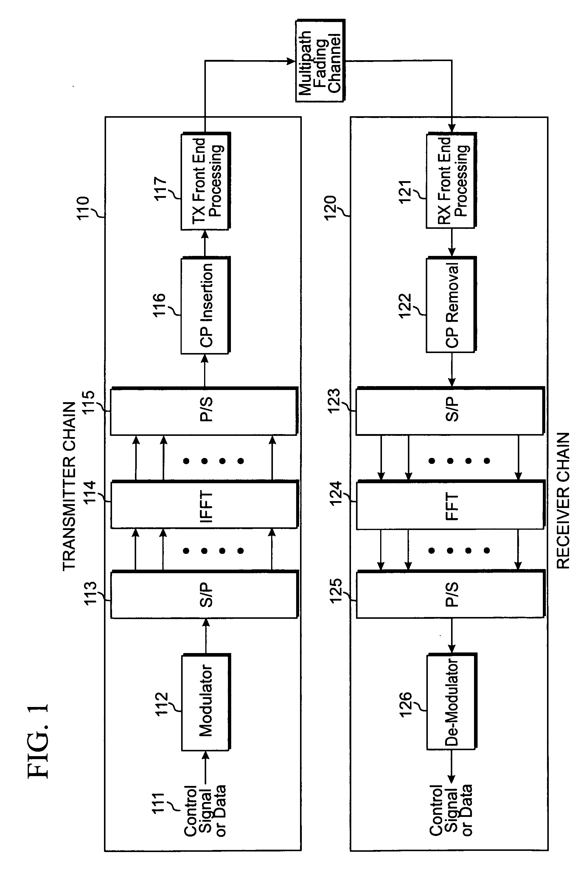
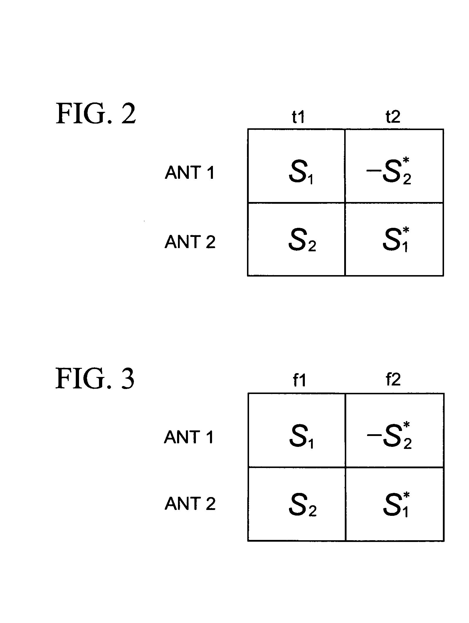
[0066]In a first embodiment according to the principles of the present invention, we describe an open-loop transmit diversity scheme where symbols S1 and S2 are transmitted via antennas ports ANTP0 and ANTP2 as shown in FIG. 5, while symbols S3 and S4 are transmitted over antenna ports ANTP1 and ANTP3, as shown in FIG. 5. The transmit matrix is given as:

[T11T12T13T14T21T22T23T24T31T32T33T34T41T42T43T44]=[S1-S2*0000S3-S4*S2S1*0000S4S3*](21)

where Tij represents symbol transmitted on the ith antenna port and the jth subcarrier or jth time slot, and i=1,2,3,4, j=1,2,3,4 for the case of four transmission antennas.

[0067]The received symbol estimates are given as:

s^1=h1*r1+h3r2*=(h12+h32)s1+h1*n1+h3n2*s^2=h3*r1+h1r2*=(h12+h32)s2+h3*n1+h1n2*s^3=h2*r3+h4r4*=(h22+h42)s3+h2*n3+h4n4*s^4=h4*r3+h2r4*=(h22+h42)s4+h4*n3+h2n4*(22)

where h1, h2, h3, h4 denote channel gains from antenna ports 0, 1, 2 and 3 respectively; n1, n2, n3, and n4 represents noise for sub-carriers 1, 2, 3, and 4 in the case of ...

second embodiment

[0069]In a second embodiment according to the principles of the present invention, reference symbols for the four transmission antennas are mapped as shown in FIG. 10. Reference signals R0, R1, R2 and R3 are mapped to physical antennas 1, 3, 2 and 4 respectively. In this case, each antenna port is defined by the reference signal transmitted on the port. That is, antenna port ANTP0 is defined by reference signal R0, antenna port ANTP1 is defined by reference signal R1, antenna port ANTP2 is defined by reference signal R2, and antenna port ANTP4 is defined by reference signal R4. Because reference signals R0, R1, R2 and R3 are mapped to physical antennas 1, 3, 2 and 4 respectively, antenna port ANTP0 corresponds to physical antenna 1, antenna port ANTP2 corresponds to physical antenna 2, antenna port ANTP 1 corresponds to physical antenna 3, antenna port ANTP3 corresponds to physical antenna 4. The large spacing between physical antenna 1 and physical antenna 3 assures that antenna po...

third embodiment

[0072]In a third embodiment according to the principles of the present invention shown in FIG. 11, CW1 is mapped to ANTP0 and ANTP1 while CW2 is mapped to ANTP2 and ANTP3 with antenna ports to physical antennas mapping as shown in FIG. 10. It can be seen that with this mapping of CW to antenna ports and the mapping of antenna ports to physical antenna mapping of FIG. 10, both codewords experience larger diversity compared to the case where ANTP0, ANTP1, ANTP2 and ANTP3 are mapped to physical antennas 1, 2, 3 and 4 respectively.


PUM


Abstract

A method for transmission is provided to generate a plurality of reference signals for a plurality of antenna ports, with each reference signal corresponding to an antenna port; to map the plurality of reference signals to a plurality of physical antennas in accordance with a selected antenna port mapping scheme, with each reference signal corresponding to a physical antenna, and the plurality of physical antennas being aligned sequentially with equal spacing between two immediately adjacent physical antennas; to demultiplex information to be transmitted into a plurality of stream blocks; to insert a respective cyclic redundancy check to each of the stream blocks; to encode each of the stream blocks according to a corresponding coding scheme; to modulate each of the stream blocks according to a corresponding modulation scheme; to demultiplex the stream blocks to generate a plurality of sets of symbols, with each stream block being demultiplexed into a set of symbols; to map the plurality of sets of symbols into the plurality of antenna ports in accordance with a selected symbol mapping scheme; and to transmit the plurality of sets of symbols via the corresponding antenna ports, with each set of symbols being transmitted via a subset of antenna ports, with, within each subset of antenna ports, the distance between the physical antennas of the corresponding antenna ports being larger than the average distance among the plurality of physical antennas.

Description

CLAIM OF PRIORITY[0001]This application makes reference to, incorporates the same herein, and claims all benefits accruing under 35 U.S.C. §119 from a provisional application earlier filed in the U.S. Patent & Trademark Office on 4 May 2007 and there duly assigned Ser. No. 60 / 924,222.BACKGROUND OF THE INVENTION[0002]1. Field of the Invention[0003]The present invention relates to a method for transmitting data in a communication system, and more specifically, a process and circuits for transmitting information by mapping antennas in a communication system.[0004]2. Description of the Related Art[0005]A typical cellular radio system includes a number of fixed base stations and a number of mobile stations. Each base station covers an geographical area, which is defined as a cell.[0006]Typically, a non-line-of-sight (NLOS) radio propagation path exists between a base station and a mobile station due to natural and man-made objects disposed between the base station and the mobile station....

Claims


Application Information

Patent Timeline
Patent Type & Authority Applications(United States)
IPC IPC(8): H04B7/00
CPCH04B7/0669H04B7/0684H04B7/0691H04L1/0003H04L1/0009H04L1/0057H04L1/0066H04L1/0606H04L1/0643H04L5/0023H04L5/005H04L27/2601H04L27/2626H03M13/1102H03M13/2957H03M13/2963H03M13/6393H04B7/0413H03M13/09H04L5/0048H04L1/0668H04L1/0656H04L1/0058H04L1/0061
Inventor KHAN, FAROOQTSAI, JIANN-ANZHANG, JIANZHONGDING, YINONG
Owner SAMSUNG ELECTRONICS CO LTD
Why Eureka
Try Eureka