Threaded fastener and fastener system

Inactive Publication Date: 2008-11-06
VAN COR DALE E
View PDF8 Cites 18 Cited by
  • Summary
  • Abstract
  • Description
  • Claims
  • Application Information

AI Technical Summary

Benefits of technology

[0060]It is a further aspect of the present invention to provide a fastener and fastening system that eliminates the need for a screw gun.
[0061]It is a further aspect o...

Problems solved by technology

Conversely, a typical screw thread is designed to b...

Method used


Image

  • Threaded fastener and fastener system
  • Threaded fastener and fastener system
  • Threaded fastener and fastener system

Examples


Embodiment Construction

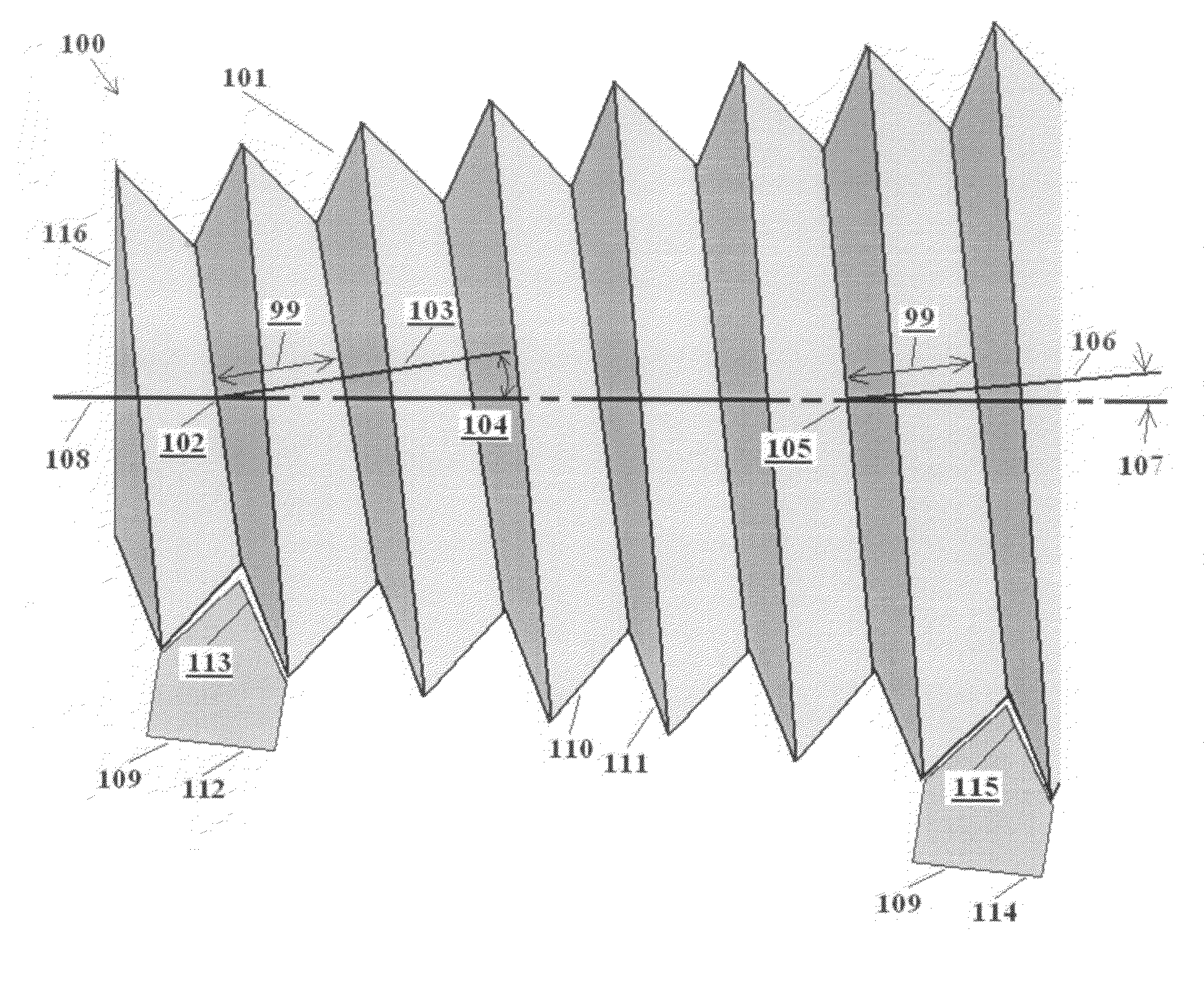
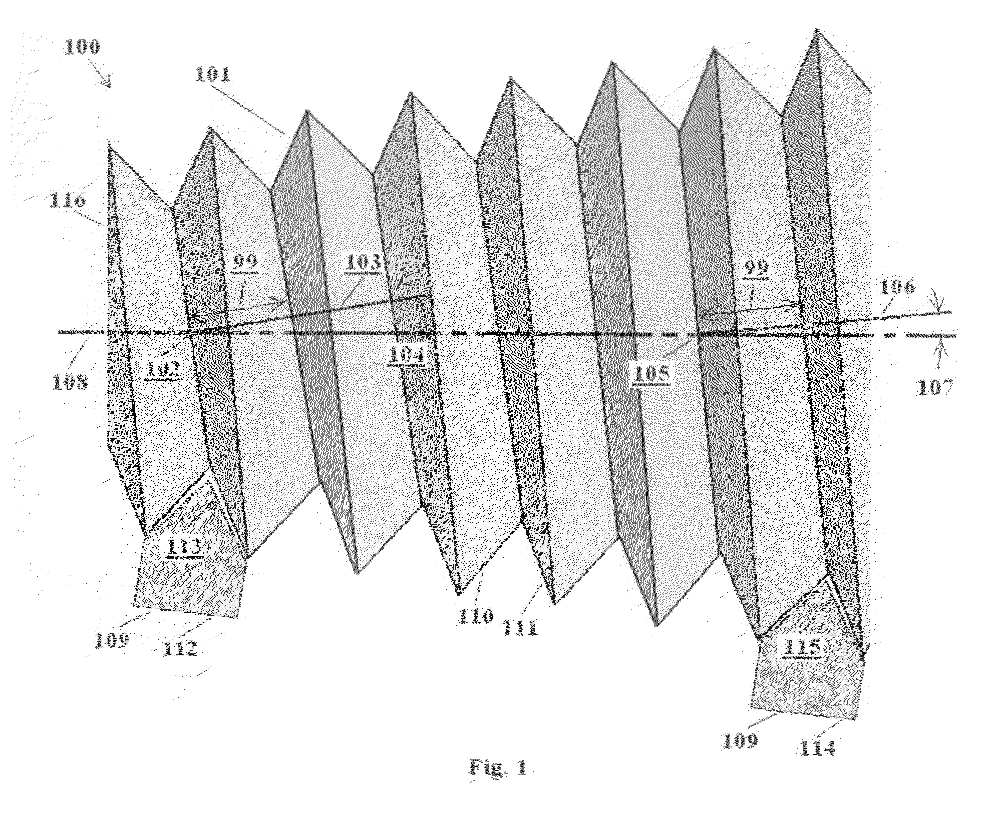
[0127]The conic thread was invented based upon observations made in developing the conic gear described in the inventor's U.S. Pat. No. 6,543,305, which is incorporated herein by reference. The conic gears described in this patent rely upon a unique conix formula, which equates a helical angle of the gear teeth with a conix angle, or angle of the cone. One of the characteristics of the conic teeth is that they are based on mathematical spirals. When these spirals are extended up the cone to a larger diameter, they flatten out approaching the horizontal. When they are extended down the cone to the apex, they approach the vertical. The teeth of conic gears have very special mathematical properties; specifically each tooth maintains an equal tangential distance 99 between its neighbors. This allows standard helical gear teeth to mesh with it.

[0128]The conic gear and conic thread share this mathematical relationship; i.e. the tangential distance between the spiraling pitch lines of the ...


PUM


Abstract

A threaded fastener and threaded fastener system. The threaded fastener includes a body having at least one outer surface and at least one thread forming a spiral about the outer surface of the body. The thread forms a plurality of crests and a plurality of roots and the tangential distance between adjacent crests is substantially constant. The threaded fastener system includes the threaded fastener and a workpiece with an opening having at least one inner surface dimensioned to mate with outer surface of the threaded fastener.

Description

CLAIM OF PRIORITY[0001]This application is a continuation in part of co-pending U.S. patent application Ser. No. 11 / 178,890, filed on Jul. 11, 2005.FIELD OF THE INVENTION[0002]The present invention relates to the field of fasteners and, in particular, to threaded fasteners and fastener systems that may be quickly and precisely engaged.BACKGROUND OF THE INVENTION[0003]Threaded fasteners, such as bolts and screws, have been used in a variety of application for many years. Conventional bolts include a thread that is a continuous helical ridge formed on the outside of a cylindrical body. This ridge is called the crest. Between each crest is a space and the bottommost point in this space is called the root. In common bolts, threads are set at an angle to the axis of the bolt, which is called the helix angle. The angle must be sloped, either upward to the right for right-hand threaded screws or upward to the left for left-hand threaded screws. Many threads form a “V” shape between crests....

Claims


Application Information

Patent Timeline
IPC IPC(8): F16B35/04
CPCF16B33/02Y10T403/1666F16B39/30F16B35/06
Inventor VAN COR, DALE E.
Owner VAN COR DALE E
Why Eureka
Try Eureka