
Remote access providing computer system and method for managing same

a computer system and remote access technology, applied in the field of remote access providing computer systems, can solve the problems of insufficient consideration of inability to fully consider the management between the user and the system, and inability to decid

Inactive Publication Date: 2008-11-06
HITACHI LTD
View PDF9 Cites 39 Cited by
  • Summary
  • Abstract
  • Description
  • Claims
  • Application Information

AI Technical Summary

Benefits of technology

[0017]In a computer system that offers a remote access service via network, it is an object of this invention to provide a technology which allows a predetermined server and other management device to acquire information on the relation among the user, client terminal, remote computer (blade) and storage area accessed by the blade and other management information in real time and manage them integrally. It is also an object of this invention to provide a system which allows the administrator to check the state of use of the blades as required, update the user environment including blades and software and execute a restoration procedure in the event of failure. Here the management device includes a physical server. The management device also includes a plurality of virtual servers mounted in one computer system. Further, one computer system includes one virtual computer system built by a clustering technique using a plurality of physical computers.

Problems solved by technology

This patent document, however, describes simply identifying a client terminal connected to the remote computer according to an IP address and authenticating the user using the client terminal and does not fully consider the management between the user and the system.
Conventional technologies have not given sufficient consideration to these problems.
In the terminal service, when the screen on the user's client terminal does not function normally, for example, the user cannot decide whether this has been caused by a communication failure or abnormal halt of OS, unlike in a situation where hardware resources are available near the user.
Conventional technologies do not take sufficient measures in these respects.
Therefore, the user using a particular blade cannot be identified from only the IP address information on the client terminal connected to that blade.
In a remote access system that uses blades for the centralized computers, assigns IP addresses of the users' client terminals to blades and allocates the storage area to individual users, since the relation among the user, client terminal, blade and storage area accessed by the blade changes from one session to another, real-time information acquisition and management is difficult depending on the conventional technology.

Method used


Image

  • Remote access providing computer system and method for managing same
  • Remote access providing computer system and method for managing same
  • Remote access providing computer system and method for managing same

Examples


first embodiment

1. First Embodiment

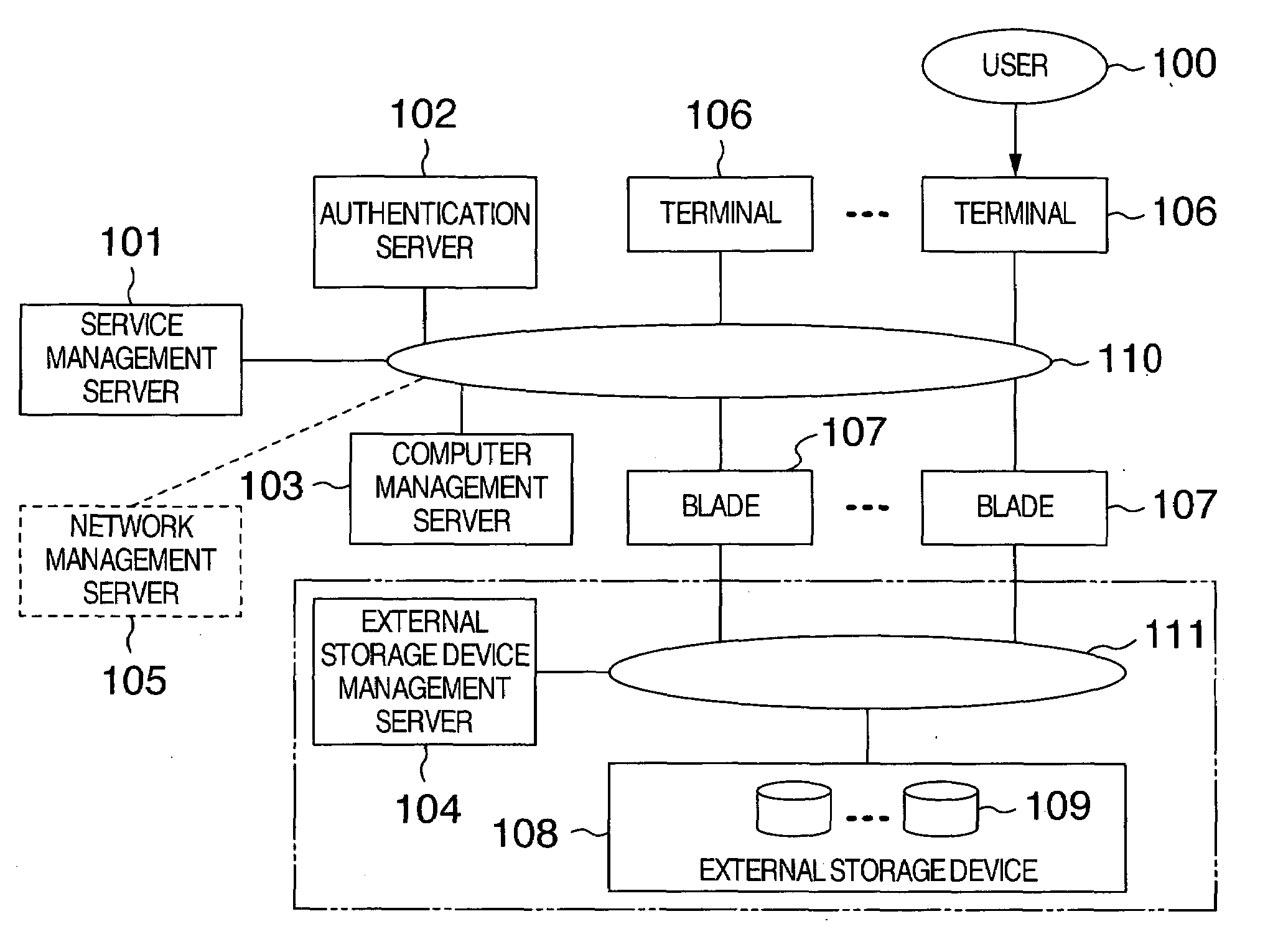
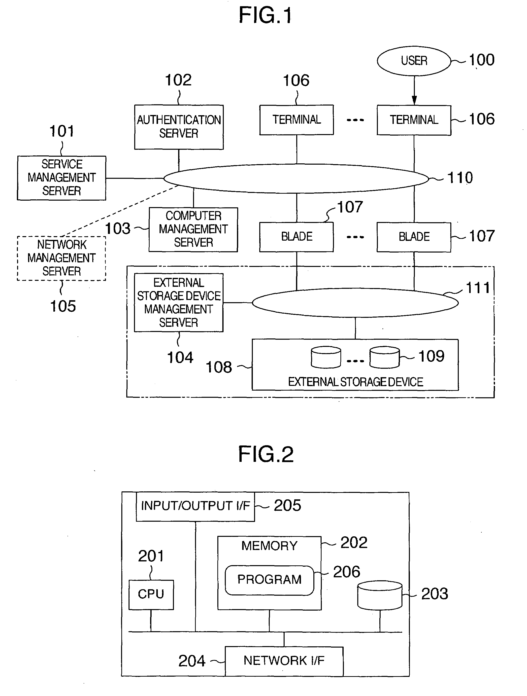
[0084]FIG. 1 shows a system configuration of one embodiment of this invention.

[0085]A network 110 interconnects a plurality of terminals 106 located at the user 100, a plurality of computers (blades) 107 (hereinafter referred to simply as blades 107) accessed by the terminals, a computer management server 103 to manage the blades 107, a service management server 101 to be described later, and an authentication server 102.

[0086]If the blades 107 are diskless blades that have no hard disk inside or other external storage devices, they are further connected to another network 111. The network 111 is connected with one or more external storage devices 108 and also with an external storage device management server 104 that manages storage areas in the external storage devices 108. Each of the external storage devices 108 divides its own storage area into one or more logical disk units 109 for management.

[0087]Although FIG. 1 shows the network 110 and the network 111 to...

second embodiment

2. Second Embodiment

[0146]As another example of this invention, a case where the service management server 101 accepts a user request will be explained.

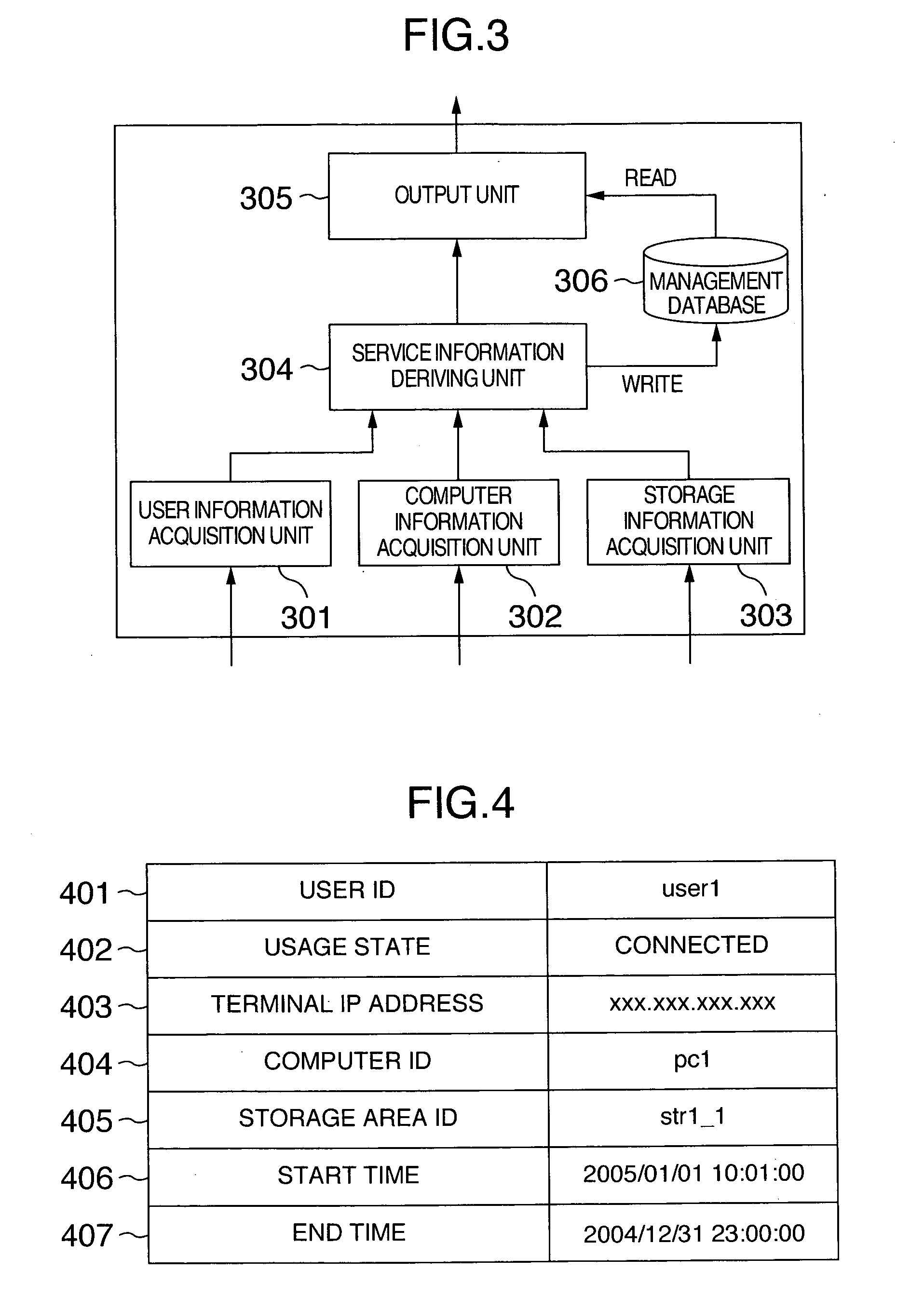
[0147]FIG. 12 shows a functional module configuration of a service management program executed by the service management server 101. The points in which this module configuration differs from that of the first embodiment of FIG. 3 are:

[0148]1) The functional module of this embodiment has additional units, which include a request accepting unit 1201 to accept a request from the user 100, an authentication unit 1202 that, at the time of request acceptance, requests an authentication of the user 100 from the authentication server 102, and a computer assignment unit 1203 that requests from the computer management server 103 an assignment of the blade 107 to the authenticated user 100.

[0149]2) Since the information on the user 100 and its terminal 106 is acquired by the request accepting unit 1201, the module does not have the user inform...

third embodiment

3. Third Embodiment

[0166]A configuration of the third embodiment that allows for the acquisition of the network information in the configuration of the first embodiment and the second embodiment is described below. The network management server 105 in the system configuration of FIG. 1 is used in the third embodiment.

[0167]The configuration of the network management server 105 is the same as shown in FIG. 2 and executes the network management program. In a system configuration having blades 107 centralized in a data center, a network in the center to which the blades 107 are connected is within the range of management.

[0168]That is, the terminal 106 of the user 100 can connect to the blades in the data center if it can reach the data center from a wide area network, a wireless network, a telephone circuitry and other network 110. The external network 110 to which the user terminal 106 is connected is outside the range of management.

[0169]The network management server 105 collects ne...


PUM


Abstract

A computer system for providing a remote access service includes a unit for acquiring information on a relation between a terminal and a user using the terminal, a unit for acquiring network information about the terminal, a unit for acquiring network information about a blade that the terminal will access, a unit for acquiring information on a relation between the blade and a storage area, and a management server for extracting information on the user and its usage information and providing these information in real time. The management server also has a unit for permitting an administrator of the management server, persons other than the user and a management program to use the blade.

Description

INCORPORATION BY REFERENCE[0001]The present application claims priority from Japanese application JP2005-347421 filed on Dec. 1, 2005, the content of which is hereby incorporated by reference into this application.BACKGROUND OF THE INVENTION[0002]The present invention relates to a computer system in which a particular user logs in to a remote computer via network by using an unspecified terminal to access a particular external storage device, and more particularly to a technology for managing this system.[0003]As the Internet becomes more widespread, there is a growing call for the user to be able to send or receive mail, access Web sites, create documents and perform other works using personal computers at places away from his or her office, at home or other places than those where such computer-related works are normally executed. To meet this demand, a system has been in service by which the user can access his or her computer at a remote location (workplace) from an electronic t...

Claims


Application Information

Patent Timeline
IPC IPC(8): G06F15/16
CPCH04L41/12H04L67/1097H04L67/303H04L67/125
Inventor KOBAYASHI, EMIKOSUGAUCHI, KIMINORIMIYAWAKI, TOUIKIKUCHI, SATOSHI
Owner HITACHI LTD
Learn More