Radiographic imaging control apparatus and method for controlling the same

a control apparatus and radiographic imaging technology, applied in the field of radiographic imaging control apparatus, can solve the problems of deteriorating image quality of radiographic image, increasing the risk of damaging the human body with x-rays, and significantly exposed human body to x-rays, so as to prevent the deterioration of the image quality of the radiographic image

Inactive Publication Date: 2008-11-13
CANON KK
View PDF6 Cites 1 Cited by
  • Summary
  • Abstract
  • Description
  • Claims
  • Application Information

AI Technical Summary

Benefits of technology

[0010]Exemplary embodiments of the present invention are directed to a radiographic imaging control apparatus capable of preventing the image quality of a radiographic image from deteriorating without excessively irradiating a subject.
[0012]According to another aspect of the present invention, a method for controlling a radiographic imaging control apparatus includes decreasing the flux of radiant rays from an upper-limit level value to a lower-limit level as time passes when a sensor is irradiated with radiant rays, and inputting a radiographic image from the sensor.

Problems solved by technology

However, in the imaging of a human body based on transmission of X-ray, it is inevitable that the human body is significantly exposed to the X-ray.
In general, detailed diagnosis of a human body requires a higher level of X-rays and increases the risk of damaging the human body with the X-rays.
On the other hand, if the level of X-ray dose is lowered for the purpose of suppressing radiation damage, the image quality of a radiographic image deteriorates due to generation and increase of noise.
Thus, the X-ray procedure can cause a problem for medical purposes.
Therefore, the subject may be unwittingly exposed to a higher level of X-ray for a long time.
Conventional radiographic imaging systems cannot prevent the image quality of a radiographic image from deteriorating without excessively irradiating the subject.

Method used


Image

  • Radiographic imaging control apparatus and method for controlling the same
  • Radiographic imaging control apparatus and method for controlling the same
  • Radiographic imaging control apparatus and method for controlling the same

Examples


first exemplary embodiment

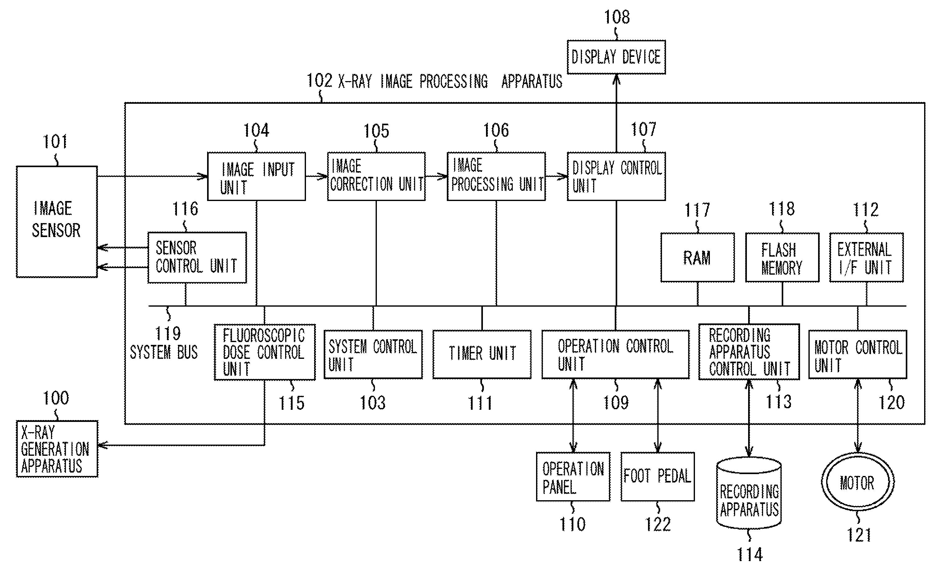
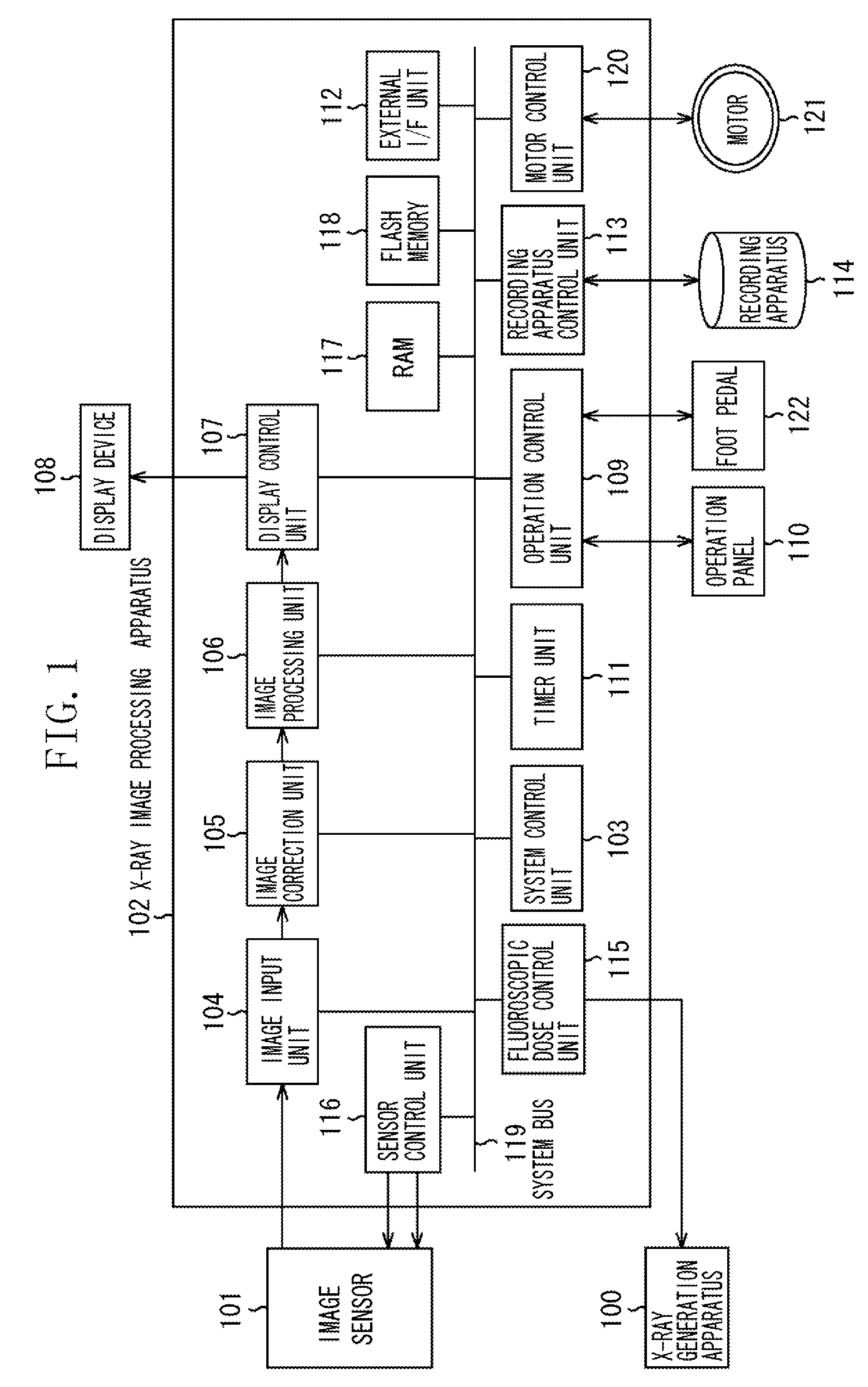
[0029]A first exemplary embodiment of the present invention is now described with reference to FIGS. 1 through 6. FIG. 1 is a block diagram illustrating an X-ray imaging control apparatus (radiographic imaging control apparatus) according to the first exemplary embodiment of the present invention.

[0030]The X-ray imaging control apparatus illustrated in FIG. 1 includes an X-ray generation apparatus (radiant ray generation apparatus) 100, an image sensor 101, an X-ray image processing apparatus (radiographic image processing apparatus or radiation dose control apparatus) 102, a display device 108, an operation panel 110, a recording apparatus 114, a motor 121, and a foot pedal 122.

[0031]The X-ray generation apparatus 100 is configured to control the X-ray flux (radiation flux) of X-rays used to irradiate the subject according to a drive voltage supplied from a fluoroscopic flux control unit 115 of the X-ray image processing apparatus 102, to obtain a fluoroscopic image (an X-ray movin...

second exemplary embodiment

[0089]A second exemplary embodiment of the present invention is described with reference to FIGS. 7 through 9. An X-ray imaging control apparatus (radiographic imaging control apparatus) according to the second exemplary embodiment of the present invention is similar in arrangement to the X-ray imaging control apparatus (radiographic imaging control apparatus) according to the first exemplary embodiment illustrated in FIG. 1.

[0090]FIG. 7 is a flowchart illustrating example processing performed by the X-ray image processing apparatus (radiographic image processing apparatus) 102 according to the second exemplary embodiment. The flowchart illustrated in FIG. 7 includes steps similar to those illustrated in FIG. 3 (first exemplary embodiment) and denoted by the same step numbers. The processing (operations) according to this flowchart is described later.

[0091]FIGS. 8A through 8C illustrate an example relationship among fluoroscopic flux, noise amount, and image correction amount accord...

third exemplary embodiment

[0125]A third exemplary embodiment of the present invention is described with reference to FIGS. 10 through 12. An X-ray imaging control apparatus (radiographic imaging control apparatus) according to the third exemplary embodiment of the present invention is similar in arrangement to the X-ray imaging control apparatus (radiographic imaging control apparatus) illustrated in FIG. 1.

[0126]FIG. 10 is a flowchart illustrating processing performed by the X-ray image processing apparatus (radiographic image processing apparatus) 102 according to the third exemplary embodiment of the present invention. The flowchart illustrated in FIG. 10 includes steps similar to those illustrated in FIG. 3 (first exemplary embodiment) and denoted by the same step numbers. The processing (operations) according to this flowchart is described later.

[0127]Furthermore, the third exemplary embodiment uses an X-ray control operation panel 1100 illustrated in FIG. 11 which is different from the X-ray control op...


PUM

PropertyMeasurementUnit
radiant ray imagingaaaaaaaaaa
radiographic imagingaaaaaaaaaa
transmission distributionaaaaaaaaaa

Abstract

A radiographic imaging control apparatus includes an input unit configured to input a radiographic image from a sensor that detects radiant ray, and a control unit configured to cause a radiant ray generation apparatus to decrease the flux of radiant ray from a predetermined maximum value to a predetermined minimum value as time passes when the radiant ray generation apparatus irradiates the sensor with radiant ray.

Description

BACKGROUND OF THE INVENTION[0001]1. Field of the Invention[0002]The present invention relates to a radiographic imaging control apparatus for controlling a radiant ray generation apparatus configured to irradiate a subject with radiant rays.[0003]2. Description of the Related Art[0004]A conventional radiographic imaging system can detect a transmission distribution of radiant rays (represented by X-rays) having been transmitted through a subject, and can be used in a medical field to help diagnose by imaging the inside of a human body.[0005]As discussed in Japanese Patent Application Laid-Open No. 2005-124975, a conventional radiographic imaging system can realize real-time suppression of radiation exposure by changing the level of X-ray dose according to a portion of a human body to be diagnosed.[0006]Furthermore, as discussed in Japanese Patent Application Laid-Open No. 2004-77709, the dose of X-rays used in the diagnosis of a human body can be changed according to a status of a d...

Claims


Application Information

Patent Timeline
Patent Type & Authority Applications(United States)
IPC IPC(8): G01N23/04G01J1/42G01J1/32
CPCA61B6/4441A61B6/542G06T5/002G06T5/003G06T5/009G06T5/20G06T2207/10121
Inventor ENDO, YOSHIYUKI
Owner CANON KK
Why Eureka
Try Eureka