High efficiency alternative/renewable powered ups system

a renewable energy and power supply technology, applied in the field of power systems, can solve the problems of reducing the efficiency of the system, so as to improve the efficiency, improve the efficiency, and reduce the cost and complexity of the system

a renewable energy and power supply technology, applied in the field of power systems, can solve the problems of reducing the efficiency of the system, so as to improve the efficiency, improve the efficiency, and reduce the cost and complexity of the system

US20080278003A1Inactive Publication Date: 2008-11-13LIEBERT

Image

  • High efficiency alternative/renewable powered ups system
  • High efficiency alternative/renewable powered ups system
  • High efficiency alternative/renewable powered ups system

Examples


Embodiment Construction

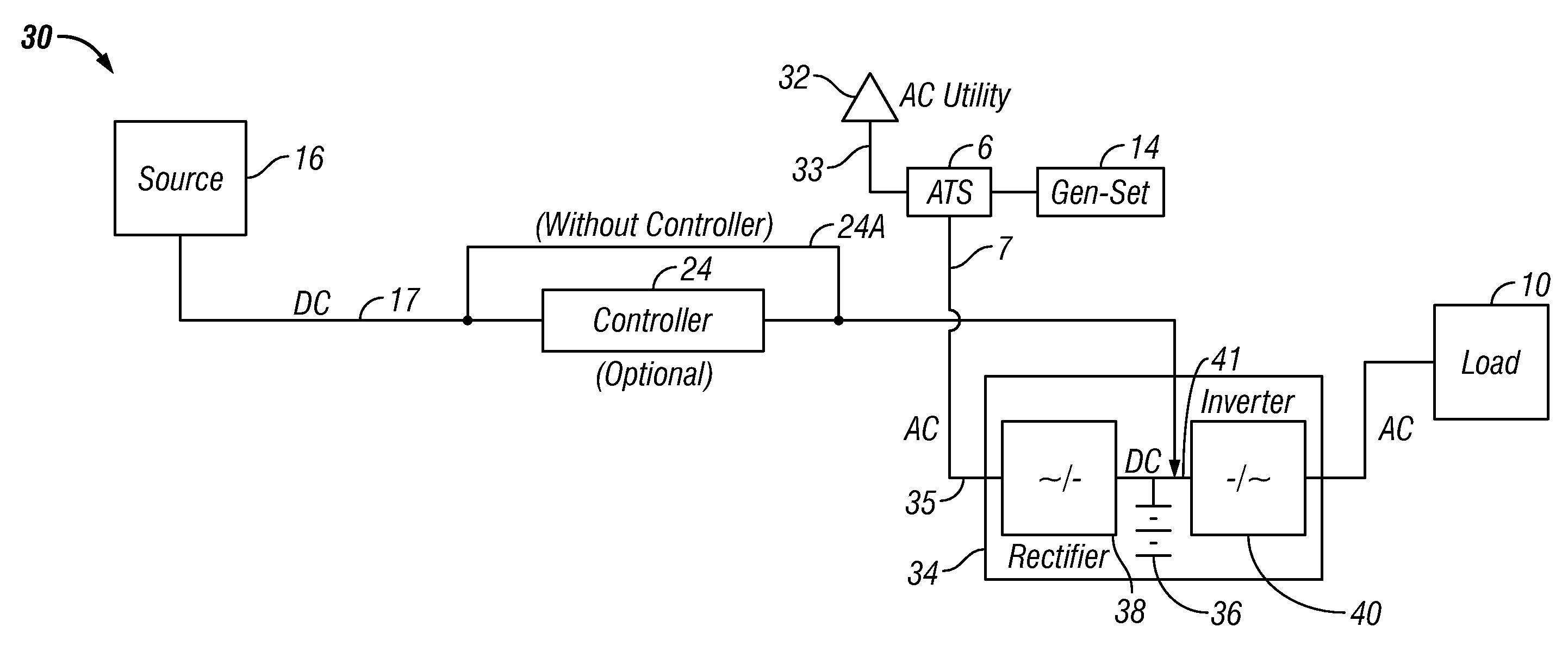
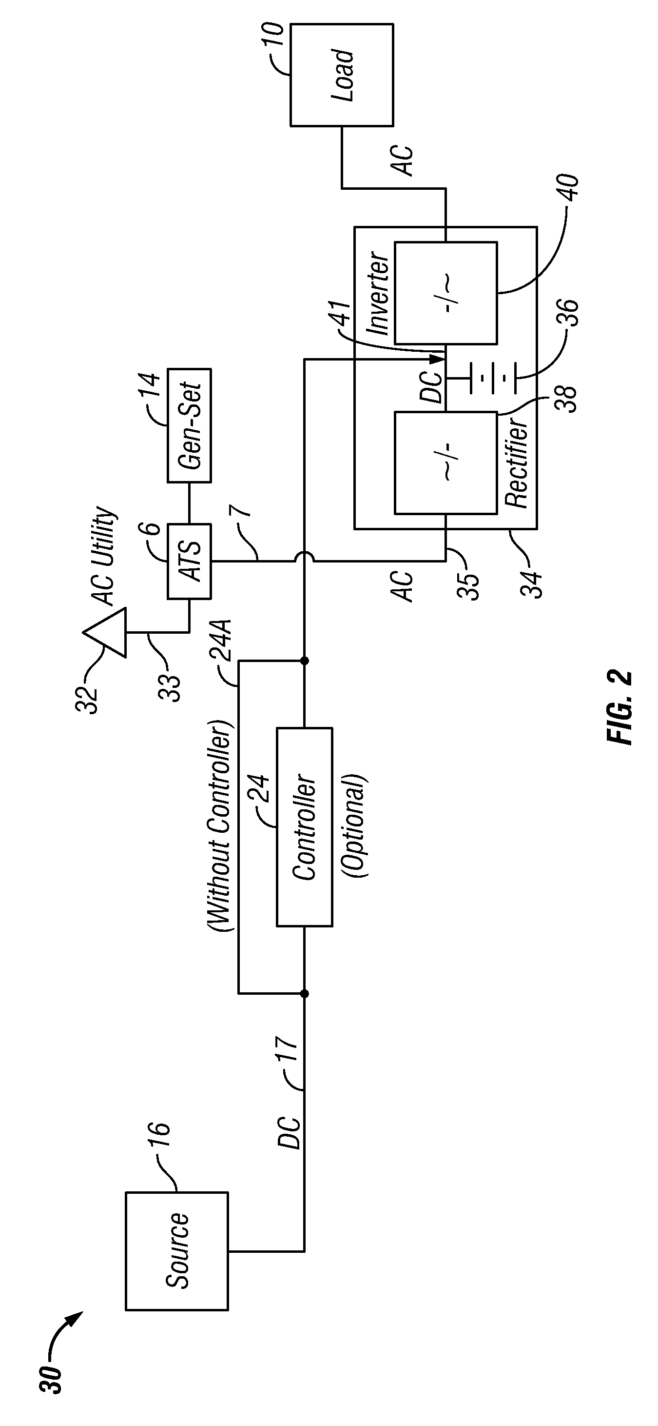
[0024]In general, the system includes several main building blocks in one or more of the embodiments disclosed. In addition to the utility power supply as a first or main source of power, the system can include: a second source of power, such as an uninterruptible power supply (UPS); associated switch gear and / or downstream interface circuits associated with the second source; upstream AC switch gear between the first and second source; and in some embodiments, an upstream generator and control interface that delays or regulates the generator operation. The system can provide additional usage of the alternative energy source and / or the second source without necessitating starting up the generator when the first source power is not present or outside acceptable conditions for such power. It is believed that the system can reduce the cost of installation by eliminating various components, particularly the grid-tie inverter, and in some embodiments, the MPPT controller. The system can ...


PUM


Abstract

The disclosure provides an efficient alternative energy uninterruptible power supply (UPS) system having a main first source of power coupled to an electrical load, comprising: a second source of power from stored energy coupled to the electrical load, the second source being adapted to supplement the first source and condition the power from the stored energy to predetermined conditions for the electrical load; an automatic transfer switch (ATS) coupled between the first source and the second source and adapted to control the first source coupling to the electrical load when the first source power is noncompliant with predetermined conditions for the electrical load; and a source of alternative energy coupled downstream of the ATS to the second source, the electrical load, or a combination thereof, wherein the source of alternative energy comprises a source of direct current (DC) power.

Description

CROSS REFERENCE TO RELATED APPLICATIONS[0001]Not applicable.STATEMENT REGARDING FEDERALLY SPONSORED RESEARCH OR DEVELOPMENT[0002]Not applicable.REFERENCE TO APPENDIX[0003]Not applicable.BACKGROUND OF THE INVENTION[0004]1. Field of the Invention[0005]The inventions disclosed and taught herein relate generally to power systems; and more specifically relate to power systems using a variety of energy sources.[0006]2. Description of the Related Art[0007]For decades, alternative energy sources have been considered in supplementing power provided by utility companies for electrical loads. Such alternative energy sources include solar energy, geo-thermal energy, wind energy, hydro energy, fuel cells, biomass and gas generated therefrom, tidal energy, and the like. To produce the necessary voltage and / or current, multiple arrays of panels, levies, dams, wind turbines, fuel cells, and so forth can be connected in series, in parallel or both, according to the needs of the system. However, the ...

Claims


Application Information

Patent Timeline
13 Nov 2008
Publication
US20080278003A1
IPC
H02J7/00
CPC
H02J9/062; Y02B10/72; Y02B10/70; Y02P80/20
Inventors
POUCHET, JACK H.; PANFIL, PETER A.