Digital Compensation For Cable Drop In A Primary Side Control Power Supply Controller

a technology of power supply controller and digital compensation, which is applied in the direction of electric variable regulation, process and machine control, instruments, etc., can solve the problems of reducing the overall system efficiency and significant drawbacks of this secondary side regulation solution, and achieves the effect of minimal voltage drop across the two sides and facilitate output regulation

Active Publication Date: 2008-11-13
DIALOG SEMICONDUCTOR INC
View PDF7 Cites 98 Cited by
  • Summary
  • Abstract
  • Description
  • Claims
  • Application Information

AI Technical Summary

Benefits of technology

[0016]The present invention is a modification to a primary side sensing power control system and method for voltage and current regulation that facilitates regulation of the output at the end of a resistive delivery cable, as compared to regulation at merely the output of the system itself. Conventional systems use “remote sensing” which requires additional wires between the power supply and the load, for insuring that regulation is with respect to the load end of the cable. The “remote sensing” method adds two sense wires that conduct little or no current, so that the voltage drop across them is minimal. This allows the controller to know what the voltage is at the output of the cable. The present invention is a modification to the control system that allows for an approximate increase of the output voltage to compensate for the approximated loss through the cable based on a current sense based on the control voltage of the loop and the knowledge of the cable resistance.

Problems solved by technology

This has the very costly problem of having to have 4 wires in the delivery cable, which is a significant cost issue in small applications.
There are at least two significant drawbacks in cost to this secondary side regulation solution, even when there is no requirement for “remote sensing”, or cable end regulation.
The second drawback is the wasted power dissipated by the sense resistor, which reduces the overall system efficiency.

Method used


Image

  • Digital Compensation For Cable Drop In A Primary Side Control Power Supply Controller
  • Digital Compensation For Cable Drop In A Primary Side Control Power Supply Controller
  • Digital Compensation For Cable Drop In A Primary Side Control Power Supply Controller

Examples


Embodiment Construction

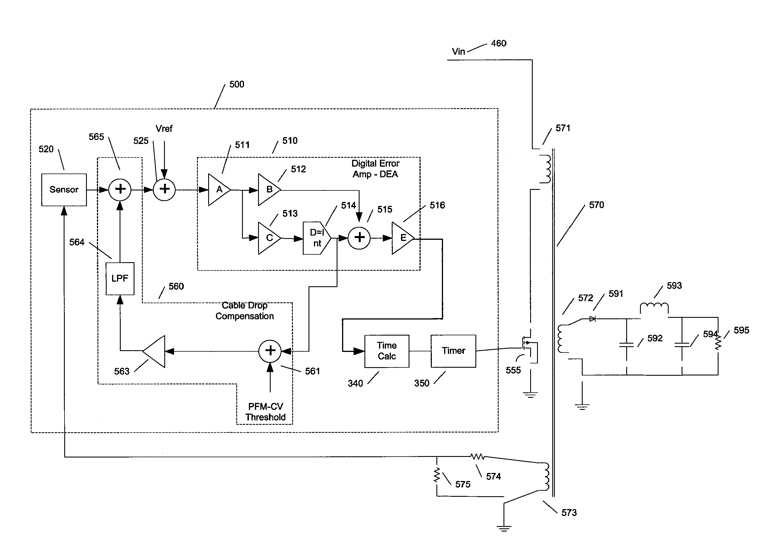
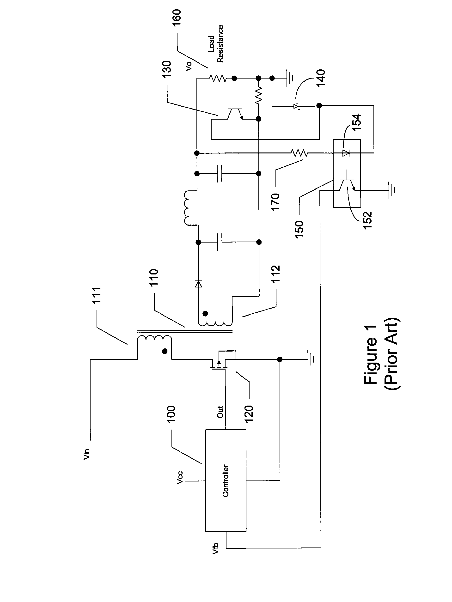
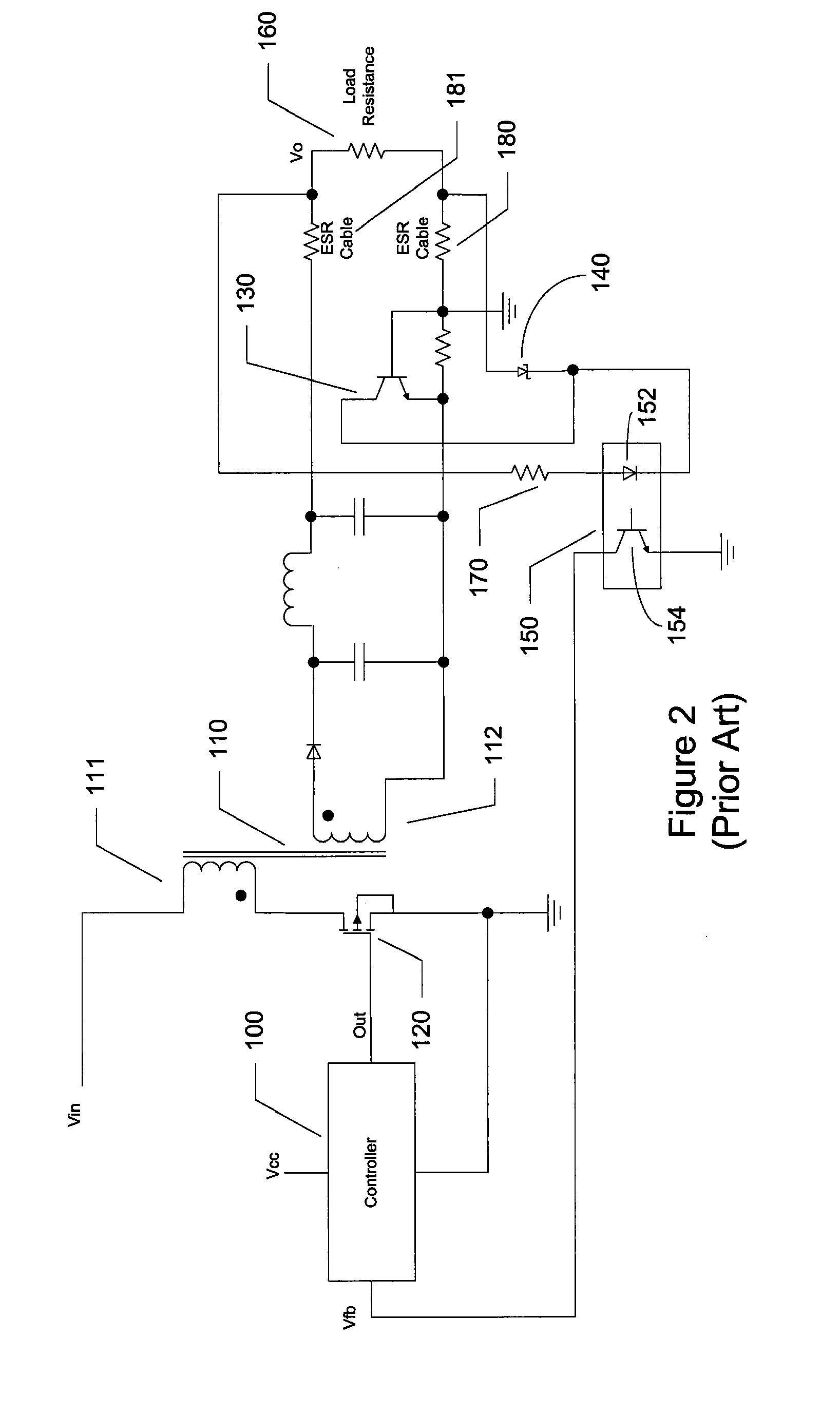
[0026]A preferred embodiment of the present invention is now described with reference to the figures where like reference numbers indicate identical or functionally similar elements. Also in the figures, the left most digit of each reference number corresponds to the figure in which the reference number is first used.

[0027]Reference in the specification to “one embodiment” or to “an embodiment” means that a particular feature, structure, or characteristic described in connection with the embodiments is included in at least one embodiment of the invention. The appearances of the phrase “in one embodiment” in various places in the specification are not necessarily all referring to the same embodiment.

[0028]Some portions of the detailed description that follows are presented in terms of algorithms and symbolic representations of operations on data bits within a computer memory and / or within a logic element. These algorithmic descriptions and representations are the means used by those ...


PUM


Abstract

The present invention is a system and a method that uses primary side sensing to regulate the output voltage at a cable end without any remote sensing of cable connections back from the load. This is accomplished by approximating the current from the control voltage in the control loop through the relationship that defines the Ton time in terms of the control voltage Vc. Once the approximation of the output current is known, it is multiplied by a known fixed cable resistance, and this value is subtracted from the feedback sensor output before it is subtracted from the digital reference. This forces the regulator to raise the output voltage by the amount of drop across the cable, causing the output of the cable to be maintained at the targeted regulation point.

Description

FIELD OF THE INVENTION[0001]The present invention is related to a power supply and more particularly to pulse width modulation (PWM) and pulse frequency modulation (PFM) controllers for regulation of voltage and / or current with primary-side sensing and feedback.BACKGROUND OF THE INVENTION[0002]Pulse width modulation (PWM) is a conventional technology used for controlling power converters to achieve output power, voltage, and current regulation. Conventional flyback power converters include a power stage for delivering electrical power from a power source to a load, a switch in the power stage that electrically couples or decouples the load to the power source, and a switch controller coupled to the switch for controlling the on-time and off time for the switch. The on-time (TON) and off-time (TOFF) for the switch can be modified by the controller based on a feedback signal representing output power, voltage, or current. The energy is stored in the transformer core gap when the switc...

Claims


Application Information

Patent Timeline
Patent Type & Authority Applications(United States)
IPC IPC(8): G05F5/00H02M3/156
CPCH02M3/33515H02M2001/0025H02M1/0025
Inventor KESTERSON, JOHN W.MUEGGE, MARK R.EASON, MARK D.
Owner DIALOG SEMICONDUCTOR INC
Why Eureka
Try Eureka