Eureka AIR delivers breakthrough ideas for toughest innovation challenges, trusted by R&D personnel around the world.

Programmable logic device with embedded switch fabric

a technology of programmable logic and switch fabric, which is applied in the direction of computation using denominational number representation, instruments, pulse techniques, etc., can solve the problems of inability to use wireless devices, limited usage to a very particular deployment, and connectivity related problems between individual devices

Inactive Publication Date: 2008-11-13
TECNICA
View PDF17 Cites 172 Cited by
  • Summary
  • Abstract
  • Description
  • Claims
  • Application Information

AI Technical Summary

Problems solved by technology

Despite the abundance of devices for transmitting and receiving information, there are connectivity related problems between the individual devices as well as the underlying infrastructures employed in the transmission and reception.
The inability of wireless devices tends to be related to the specific implementation utilized in the design.
Thus, while the general hardware elements are similar, the design limits the usage to a very particular deployment.
Other devices suffer from the same difficulties, and accessories and other implementation schemes have to be used to provide interconnectivity.
SDR is more easily implemented in wireless devices and the handheld devices employing SDR generally have performance limitations that are dependent on the battery power, size, weight, and cost requirements.
As a user travels outside of the coverage area of its chosen wireless data network, the radio signal is lost.
But, the roaming agreements only help to alleviate coverage limitations and cannot provide for seamless, widespread operation due to the existence of wireless data network incompatibilities.
While portable radio devices have emerged offering limited operation on multiple frequency bands, few commercial devices have been realized that can provide multiple communication modes.
A problem with such a radio is that when a user moves from a “home” location to a “remote” location, the radio is not easily configurable to communicate at the remote location, as that location has coverage via a different service.
For example, when a user travels overseas, the user's radio does not support a service that is available at the home location.
Another problem is when existing radios need to update or receive a software application (e.g., wireless email, operating system).
Typically, a radio is taken into a service center to update or receive an application so that the radio can provide a service associated therewith, which is time consuming and expensive.
Frequently, users of radios such as police, federal agency, and military encounter difficulties when attempting to interoperate communication equipment.
Frequently, existing systems do not allow interoperability between military and local communication equipment.
Thus, a problem with existing systems is interoperability between communications equipment, and the additional complexity and expense to “translate” from one communication technique to another.
Another problem with existing radios, including original manufactured and those serviced / repaired, is verifying when a radio meets a predetermined specification for communications.
The divergent 2G standards (adopted by large groups of end-users around the globe) often frustrate business travelers who communicate with their customers or offices while traveling from one network type to another as they cannot use the same device without significant enhancements / adjustments to deal with incompatible systems.
There are many published materials related to SDR and various designs and proposals of operation, however there is still a general disagreement as to the optimal form, features, or unifying standard.
If the system is unable to obtain sufficient information from a base station prior to losing a current wireless data network connection, the radio is not able to dynamically select a new software configuration and wireless data network without directions from the base station.
However, despite all the attempts in the art, there has yet to emerge a scheme that fulfils the industry requirements and addresses all the aforementioned problems.

Method used


Image

  • Programmable logic device with embedded switch fabric
  • Programmable logic device with embedded switch fabric
  • Programmable logic device with embedded switch fabric

Examples


Embodiment Construction

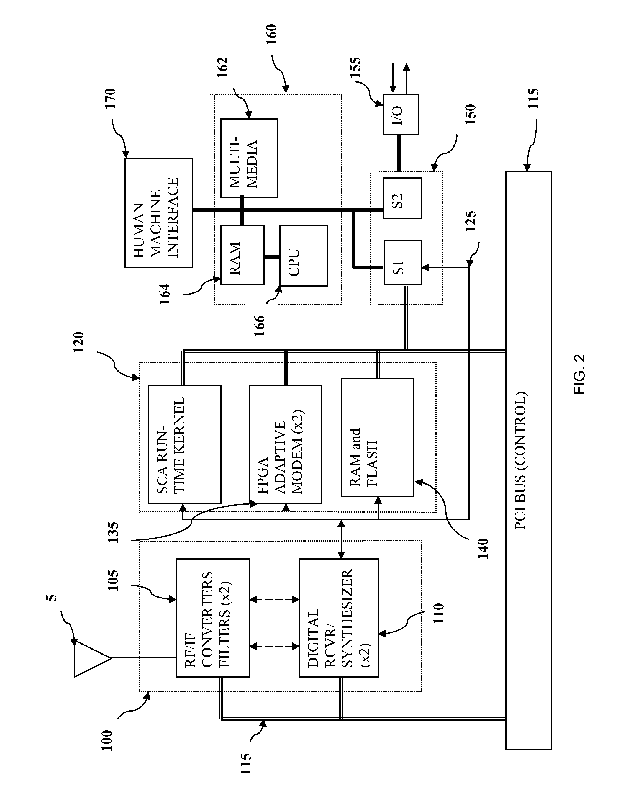
[0054]As noted herein, the SDR architecture is based upon a high-level generic model with specific functional blocks connected via open interface standards recommendations. The SDR architecture supports a plurality of domains including hand-held, mobile, and base-station (or fixed site). Software is implemented by controlling the characteristics of equipment / device subsystems through hierarchical and peer level modules that support scalability and flexible extensions of applications. Modularity allows implementation of software applications within open systems, and between the modules are more defined interfaces. Within a module the developer implements functionality in the most effective way for the particular application.

[0055]One aspect of the present invention is a self-booting software defined radio (SDR) module that may be embodied as a PCMCIA, Compact Flash, or other “plug in” form factor module. The performance characteristics of the module, including its RF carrier frequenc...


PUM


Abstract

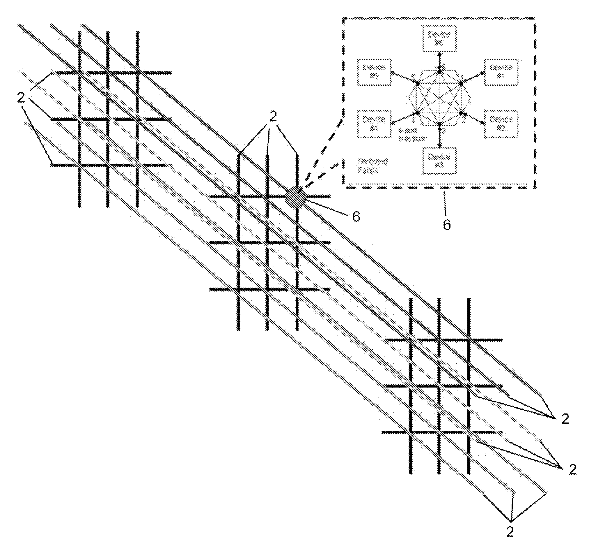
The invention in the simplest form is a programmable logic device consisting of gate arrays, external I / O endpoints, and an embedded switch fabric configurable for connecting gates to gates, endpoints to endpoints and gates to endpoints. The architecture may employ a fabric interface of non-blocking crossbar switches for making complex bus connections of multiple devices to facilitate high speed processing.

Description

RELATED APPLICATIONS[0001]This application discloses and claims only subject matter disclosed in, and names the inventor named in, and is therefore a continuation of, pending U.S. application Ser. No. 10 / 618,950, filed Jul. 14, 2003, which claims priority to U.S. Application No. 60 / 395,871, filed Jul. 12, 2002, both of which are incorporated herein in their entirety by reference.STATEMENT OF GOVERNMENT INTEREST[0002]Portions of the present invention may have been made in conjunction with Government funding under contract number F30602-03-C-0183, and there may be certain rights to the Government.FIELD OF THE INVENTION[0003]The present invention relates to a programmable logic device (PLD) with embedded switch fabric, and more particularly to PLDs having an embedded crossbar switch fabric interface, a gate array, and I / O endpoints, where the embedded fabric is connectible to gates, I / O endpoints, and internal processors.BACKGROUND OF THE INVENTION[0004]As evident from the widespread u...

Claims


Application Information

Patent Timeline
Patent Type & Authority Applications(United States)
IPC IPC(8): H03K19/177G06F9/00G06F9/445H04B1/40H04M
CPCG06F9/4401H04B1/0003H04B1/0028H04B1/406
Inventor MUROTAKE, DAVID K.
Owner TECNICA
Why Eureka
Eureka Blog
Learn More