n-Buck cascade converter with single active switch

a technology of active switch and cascade converter, which is applied in the direction of power conversion system, electrical apparatus, dc source parallel operation, etc., can solve the problems of limited conversion ratios, complex control circuitry, and increased total losses mainly, so as to avoid complex control circuitry and reduce voltage/current output. the effect of high efficiency

Inactive Publication Date: 2008-11-13
ORTIZ LOPEZ GUADALUPE +2
View PDF1 Cites 9 Cited by
  • Summary
  • Abstract
  • Description
  • Claims
  • Application Information

AI Technical Summary

Benefits of technology

[0006]In this patent, a topology for an n-buck cascade converter with a single active switch is proposed which will allow the production of a lower voltage/higher current output. The cascade configuration allows a DC conversion ratio of Un where U is the duty ratio, using a minimum number of active switches while avoiding a complex control circuitry. This converter is comprised of n i...

Problems solved by technology

A possible solution to this problem is to use n-stages connected in cascade using n-active switches; however, the major drawbacks are: (a) the total losses are increased mainly by the active switches, and (b) a more complex control circuitry is required.
In practice, the maximum and the minimum attainable conversion ratios for the conventional converters are limited by the characteristics of the switching devices.
Also, when the duty ratio is close to 0 or 1, a great deterioration on the output voltage and inductor current signals occur and; therefore, in the control signal....

Method used


Image

  • n-Buck cascade converter with single active switch
  • n-Buck cascade converter with single active switch
  • n-Buck cascade converter with single active switch

Examples


Embodiment Construction

[0016]A scheme that provides a wider conversion ratio without a transformer is a cascade converter. This scheme consists of n-conventional converters connected in cascade with n-active switches. The conversion rate, for duty ratios Ui, is

∏i=1nUi.

A second scheme consists of an n-buck cascade converter with a single active switch. The conversion rate, for a duty ratio U is Un. An advantage of the last scheme is that the total efficiency is much better because of the use of a single switch.

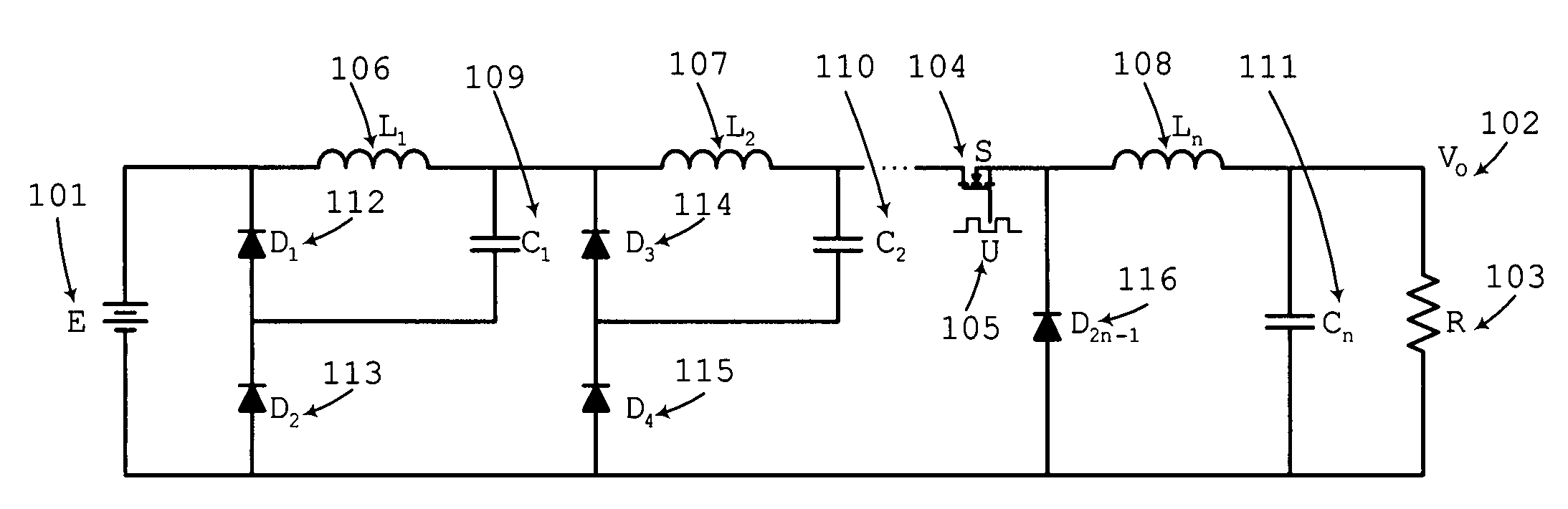
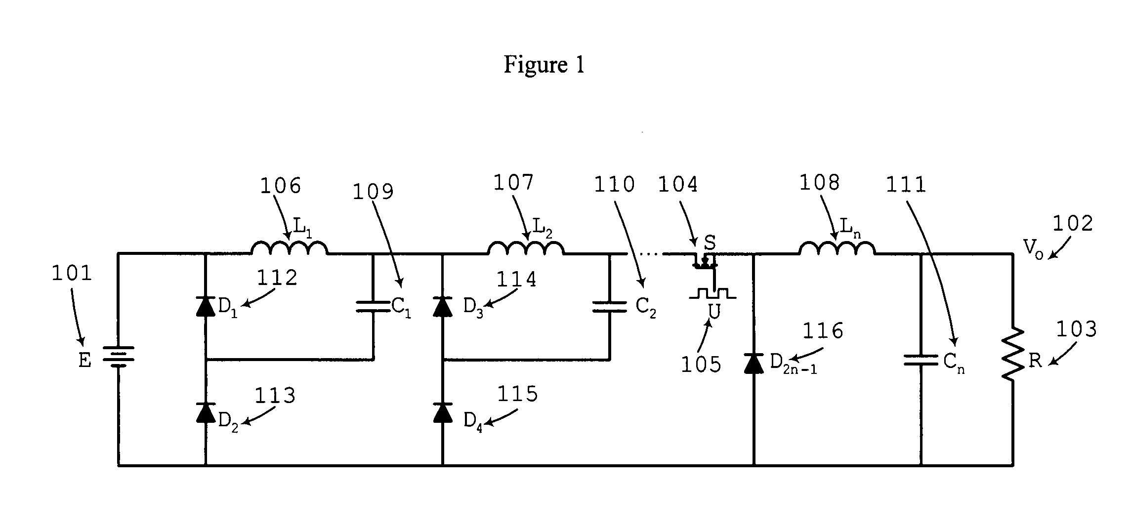
[0017]The block diagram of the n-buck cascade converter is shown in FIG. 1 where E is the input voltage from an unregulated power source 101, Vo is the output voltage 102 and R is the load 103. The MOSFET transistor 104 is operated using a switching signal with a duty ratio U 105. This converter requires n inductors L1, L2, . . . , Ln 106, 107, 108 all connected is series, n capacitors C1, C2, . . . , Cn 109, 110, 111 all connected in parallel and (2n-1) diodes 112, 113, 114, 115, 116. This converter...


PUM


Abstract

An n-buck cascade converter, where the DC conversion ratio is Un where U is the duty ratio. The converter comprises n inductors, n capacitors, (2n-1) diodes and a MOSFET transistor. The cascading configuration uses the minimum number of active switches while avoiding complex control circuitry. It is assumed that this converter operates in continuous condition mode, i.e., all the inductor currents never decay to zero. The corresponding formulae for the ripples in the capacitor voltages and the inductor currents are given. This allows designing in principle a specific converter following some specifications.

Description

BACKGROUND OF THE INVENTION[0001]During the last two decades, a great number of applications for DC-DC converters have been reported. New technological developments require power supplies with significant step-down voltages. A possible solution to this problem is to use n-stages connected in cascade using n-active switches; however, the major drawbacks are: (a) the total losses are increased mainly by the active switches, and (b) a more complex control circuitry is required. An alternative solution is to use an n-buck cascade converter with a single active switch. This converter, in accordance with the present invention, provides a wider conversion rate producing a lower voltage / higher current output.[0002]Switching converters are electronic circuits that allow energy conversion from one DC level to another. These switching converters are widely used in the power supply industry. They operate under the principle of storing energy in an inductor L, from an unregulated power source, d...

Claims


Application Information

Patent Timeline
IPC IPC(8): H02J1/10
CPCH02M3/155
Inventor ORTIZ-LOPEZ, GUADALUPELEYVA-RAMOS, JESUSDIAZ-SALDIERNA, LUIS HUMBERTO
Owner ORTIZ LOPEZ GUADALUPE
Why Eureka
Try Eureka