Strong distributed feedback semiconductor laser

a semiconductor laser and distributed feedback technology, applied in semiconductor lasers, laser optical resonator construction, laser details, etc., can solve the problems of difficult control of distributed feedback, difficult to achieve technologically, and loss modulation of feedback, so as to achieve simple control and implement the effect of not affecting the laser's performance levels

Active Publication Date: 2008-11-13
THALES SA
View PDF3 Cites 4 Cited by
  • Summary
  • Abstract
  • Description
  • Claims
  • Application Information

AI Technical Summary

Benefits of technology

[0011]In this context, the present invention proposes a new type of distributed feedback laser that uses index modulation and is based on a technology that is easier than those of the prior art. Thus, the technology that is to be described below makes it possible to produce strong distributed feedback lasers; it is technologically simple to implement and to control, and does not affect the laser's performance levels.

Problems solved by technology

The main drawback of this technology is that it entails interrupting the growth between the active area and the waveguide in order to etch the grating then to carry out a new epitaxial growth step.
This step is technologically difficult to perform, notably because an epitaxy must be performed on the grating, therefore on a surface that is not perfectly flat.
This makes the feedback difficult to control.
On the other hand, its main defect is that the distributed feedback is obtained by loss modulation.
This introduces additional losses, increasing the laser threshold and therefore degrading the laser's performance.
Furthermore, the distributed feedback is, as with the buried grating technology, difficult to control because it is very sensitive to the accuracy of the etched pattern.
Finally, the distributed feedback that is obtained is also linked to the optical losses introduced by the metal and the constituent materials of the waveguide, which constitutes another parameter that is difficult to control.
To sum up, the existing technologies for developing distributed feedback lasers are generally difficult to implement and to control and can degrade the laser's performance.

Method used


Image

  • Strong distributed feedback semiconductor laser
  • Strong distributed feedback semiconductor laser
  • Strong distributed feedback semiconductor laser

Examples


Embodiment Construction

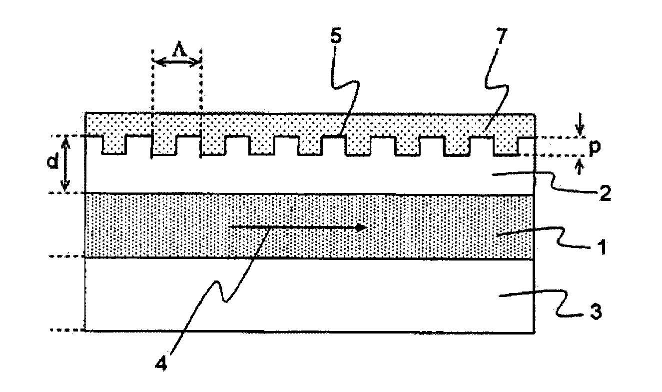
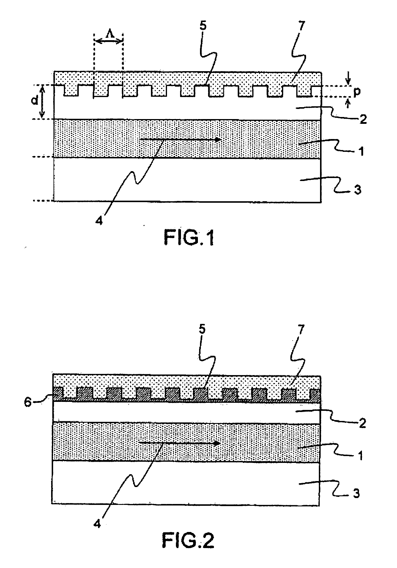
[0034]FIG. 1 is a simplified diagram of the laser according to the invention. The key lies in understanding the physical phenomena that occur in the laser and how to control them.

[0035]In practice, in the inventive laser, thanks to an appropriate stack of layers forming the active area 1, and thanks to a top waveguide 2 consisting of a non-doped or weakly-doped (that is, introducing a variation of the refractive index less than 10%) semiconductor material, a coupling is obtained between the surface waves, also called plasmons, of the metal structure 7 which covers the grating 5 located above the top waveguide 2 and the modes guided by the semiconductor layers 2 and 3. This coupling introduces an index modulation without additional loss. This physical phenomenon is described in the document by M. CARRAS and A. DE ROSSI entitled “Photonic modes of metallodielectric periodic waveguides in the midinfrared spectral range”, Physical Review B, 74, 235120 (2006). Moreover, the French patent...


PUM


Abstract

The present invention relates to a strong distributed feedback semiconductor laser. More specifically, the invention implements a top optical waveguide (2) for semiconductor lasers having a surface metallic grating (5) making it possible to obtain a stable and controlled distributed feedback, using a simple and robust technology. In the inventive laser, which comprises an active area (1) having an effective refractive index (neff) in which a light wave is propagated with a wavelength (λ), the top waveguide (2) is made of a weakly-doped material and the periodic grating (5) depth (p) is
[λ4×neff]
plus or minus 50%, the low precision needed being one of the advantages of the inventive laser.

Description

RELATED APPLICATIONS[0001]The present application is based on, and claims priority from, French Application Number 07 03389, filed May 11, 2007, the disclosure of which is hereby incorporated by reference herein in its entirety.TECHNICAL FIELD[0002]The present invention relates to a distributed feedback semiconductor laser. More specifically, the invention implements an optical waveguide for semiconductor lasers having a surface metallic grating making it possible to obtain a stable and controlled distributed feedback, using a simple and robust technology.BACKGROUND OF THE INVENTION[0003]It is known that the first objective of distributed feedback is to maximize the elimination of the laser's secondary modes. A second objective is generally to reduce the mirror losses, that is, the losses due to the finite length of the laser cavity.[0004]Currently, there are two main technologies for producing distributed feedback (DFB) lasers.[0005]These two known technologies are on the one hand ...

Claims


Application Information

Patent Timeline
Patent Type & Authority Applications(United States)
IPC IPC(8): H01S5/10
CPCH01S5/1228
Inventor CARRAS, MATHIEUDE ROSSI, ALFREDO
Owner THALES SA
Why Eureka
Try Eureka