Measuring Device, Especially Temperature Measuring Transducer

a technology of measuring device and transducer, which is applied in the direction of heat measurement, instruments, pulse technique, etc., can solve the problems of triggering an immediate installation shutdown and entail considerable expense, and achieve the effect of saving high costs, reducing the number of system shutdowns, and high accuracy

Inactive Publication Date: 2008-11-13
SIEMENS AG
View PDF3 Cites 23 Cited by
  • Summary
  • Abstract
  • Description
  • Claims
  • Application Information

AI Technical Summary

Benefits of technology

[0007]The advantage of the invention is that it allows the value of the resistor to continue to be measured when a line break occurs in one of the two lines which are connected to same side of the resistor. A line break of a line with which the resistor is connected to an evaluation device thus does not necessarily result any more in a failure of the measuring device. Especially in a measuring transducer for measuring a process temperature in an automation technology installation, the process temperature can continue to be measured with sufficiently high accuracy and thereby the automated installation can remain in operation. The number of system shutdowns is thus reduced and associated high costs are saved. Since the measuring transducer continues to deliver valid measurement values despite the line break, repair work does not have to be dealt with immediately when a defect occurs but can be undertaken within the framework of scheduled maintenance work. The high costs involved with a redundant arrangement of measuring transducers can advantageously be avoided by the invention.
[0008]If the influence of the line resistance of the second line on the measuring result is compensated for this has the advantage that, even after the occurrence of the line break, highly accurate measurements are still possible. For example on failure of a line of a four-wire circuit, a switchover can be made to measurement with a three-wire circuit which still delivers high measurement accuracy.
[0009]The state of the lines by which a measuring resistor is connected to an evaluation device can be checked in a particularly si

Problems solved by technology

Depending on the safety concept of the installation, this can have the disadvantage of triggering an immediate shutdown of the installation.
The disadvantage of a redundant arrangement at measuring transducers however is that it entails consid

Method used


Image

  • Measuring Device, Especially Temperature Measuring Transducer
  • Measuring Device, Especially Temperature Measuring Transducer
  • Measuring Device, Especially Temperature Measuring Transducer

Examples


Embodiment Construction

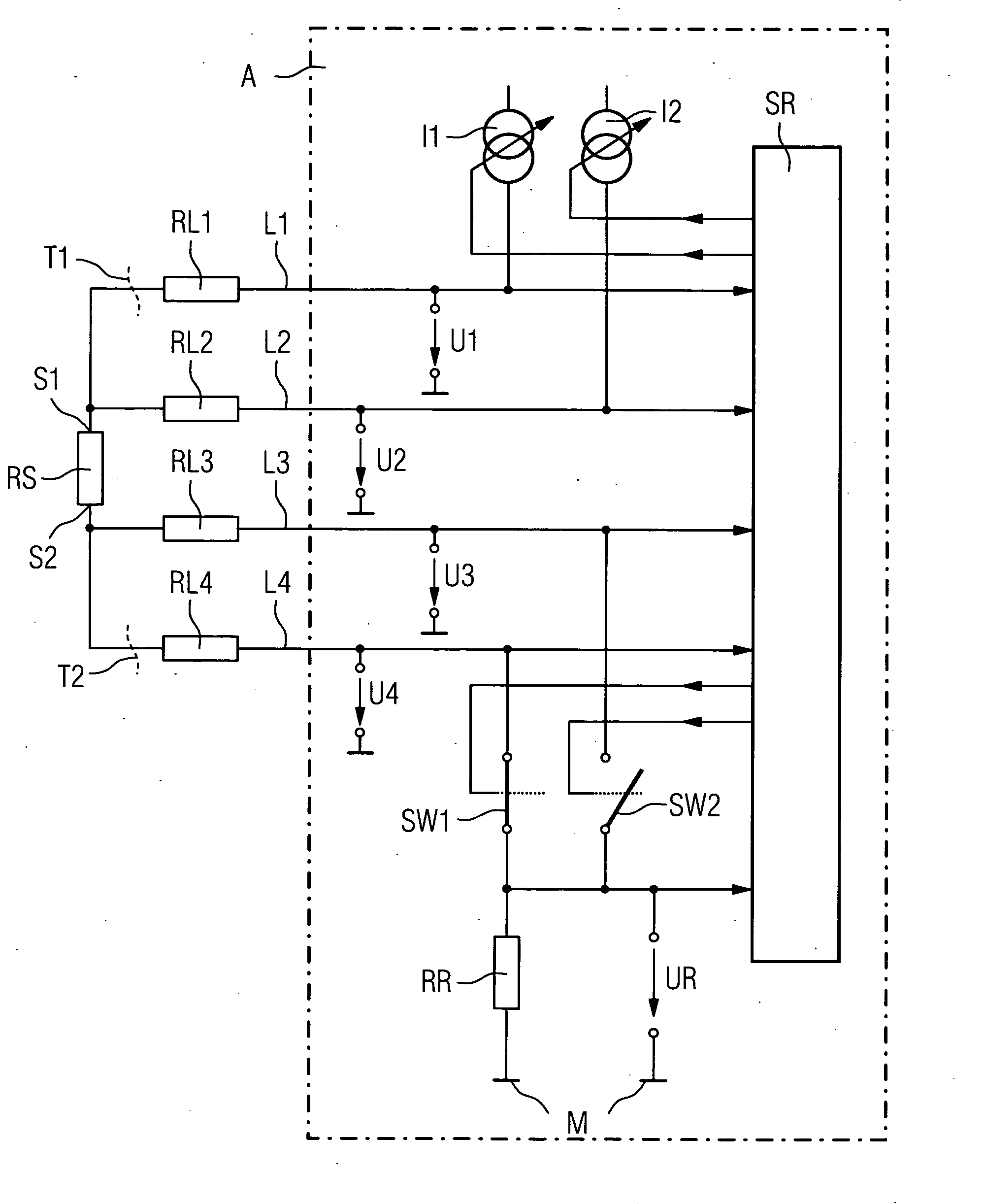
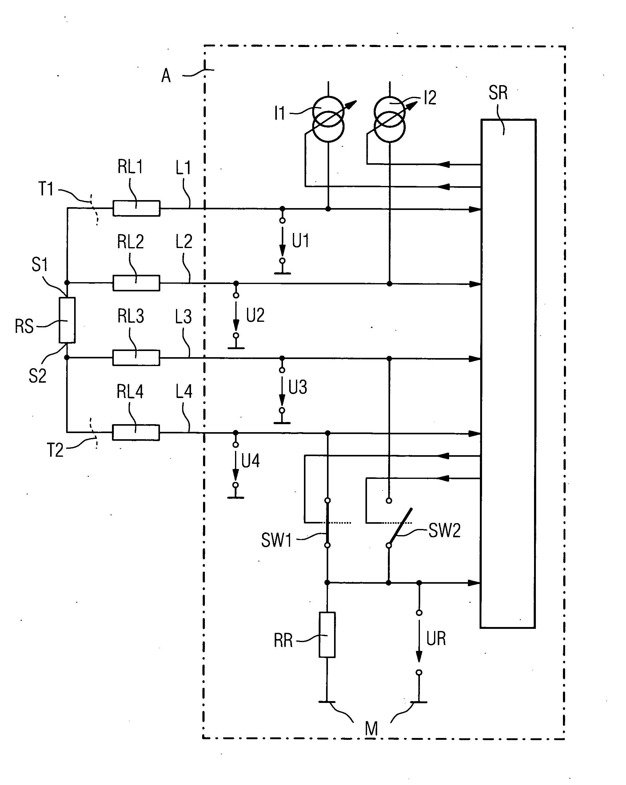
[0014]The FIGURE shows a basic diagram of a measuring device with an electrical resistor RS, which in a temperature measuring transducer varies its resistance values depending on a temperature. The resistor RS is connected by four lines L1, L2, L3 and L4 to an evaluation device A. The circuit in this case is what is known as a four-wire circuit, in which two lines L1 and L2 are connected to a first side S1 of the resistor RS and two lines L3 and L4 to a second side S2 of the resistor RS. The amount of electrical resistance to which the lines L1 . . . L4 are subjected is taken in account by including concentrated resistances RL1, RL2, RL3 or RL4 in the circuit diagram. The evaluation device A contains a control and processing unit SR, which can essentially be implemented by a microprocessor with a program memory for a suitable operating program and with a data memory for storing variable values. Two controllable current sources 11 and 12 which are connected to the lines L1 or L2 can ...


PUM


Abstract

The invention relates to a measuring device, in particular a temperature measuring transducer, comprising an electrical resistor, which alters its value based on a chemical or physical variable that is to be measured and which is connected to an evaluation device via at least three lines. Said evaluation device checks the lines for line breaks and if such a break has occurred, switches from a four-wire circuit to a three- or two-wire circuit as required, in order to permit the continuation of the measuring operation. This improves the reliability of the measuring device.

Description

CROSS REFERENCE TO RELATED APPLICATIONS[0001]This application is the US National Stage of International Application No. PCT / EP2004 / 014440, filed Dec. 17, 2004 and claims the benefit thereof. The International Application claims the benefits of German Patent application No. 103 59 988.6 filed Dec. 19, 2003. All of the applications are incorporated by reference herein in their entirety.FIELD OF THE INVENTION[0002]The invention relates to a measuring device, especially a temperature measuring transducer, with an electrical resistor, which alters its value depending on a chemical or physical variable.BACKGROUND OF THE INVENTION[0003]A temperature measuring transducer with such a measuring device is for example known from U.S. Pat. No. 5,317,520. The measurement of a temperature as a chemical or physical variable is undertaken with an electrical resistor, which alters its value depending on this variable. This resistor is connected in a three-wire or four-wire circuit to an evaluation de...

Claims


Application Information

Patent Timeline
IPC IPC(8): G01K15/00G01R31/00G05B23/02
CPCG01K7/20G01K15/00
Inventor BURMEISTER, DIRKCHEMISKY, ERIC
Owner SIEMENS AG
Why Eureka
Try Eureka