Method and apparatus for synchronizing data in utility system

a utility system and data synchronization technology, applied in the field of utility systems, can solve the problems of insufficient time homogeneity in practical applications, insufficient timetamps to accurately describe temporal moments, and insufficient measurement data scalar without context of when

Active Publication Date: 2008-11-13
SCHNEIDER ELECTRIC USA INC
View PDF11 Cites 18 Cited by
  • Summary
  • Abstract
  • Description
  • Claims
  • Application Information

AI Technical Summary

Benefits of technology

[0009]The monitoring device may be a power meter and may further include a cycle counter that counts the number of cycles of the electrical voltage or current on the power conductor, wherein the data indicative of the detection of the synchronization signal includes a time associated with the detection of the synchronization signal and the cycle count associated with the detection of the synchronization signal. The synchronization signal may include a plurality of pulses, the monitoring device converting the plurality of pulses to a corresponding digital word indicative of at least a control function, a reset function, a configuration function, or a utility demand interval function. The control function may include at least one of an instruction that causes a load coupled to the monitoring device to be turned on or off, or an instruction that causes an actuator a circuit breaker coupled to the monitoring device to change states. The reset function may include at least one of an instruction to adjust a counter or value related to an electrical characteristic or an instruction to reset the monitoring device. The configuration function may include an instruction to configure a parameter of the monitoring device, the parameter including a value indicative of the at least one characteristic of the synchronization signal. The utility demand interval function may include an instruction to increment or reset a utility demand interval counter.
[0010]According to other embodiments of the present invention, a method of communicating a synchronization signal that is interpreted simultaneously by a plurality of monitoring devices in a power monitoring system includes: generating a synchronization signal having at least a magnitude and a duration; coupling the synchronization signal via power line communication onto one or more power conductors to which the plurality of monitoring devices are coupled at periodic time intervals that are determined by a reference clock external to the plurality of monitoring devices; receiving, simultaneously at each of the plurality of monitoring devices, the synchronization signal; detecting at least one of the magnitude or the duration of the synchronization signal; and responsive to the detecting, storing data in memory indicative of the detection of the synchronization signal.
[0011]According to other aspects of the present invention, the detecting may include filtering the synchronization signal at a harmonic (or interharmonic) component of the fundamental frequency of the voltage or current in the one or more power conductors. The method may further include encoding in the synchronization signal at least one of control information, reset information, configuration information, or utility demand interval information, the synchronization signal comprising a plurality of pulses transmitted in a sequence that is decoded and converted into a corresponding digital word by each of the plurality of monitoring devices. The storing may include adjusting an on-board clock in at least one of the plurality of monitoring devices to be synchronized with the reference clock.
[0012]The method may further include counting, in at least one of the plurality of monitoring devices, the number of peaks in the voltage or current in the one or more power conductors and storing the number of peaks in a cycle count counter on the at least one of the plurality of monitoring devices, wherein the storing includes resetting the cycle count counter. The method may further include determining, in at least one of the plurality of monitoring devices, an outage time based on the number of peaks actually counted by the at least one of the plurality of monitoring devices during a time interval between two consecutive synchronization signals and on the number of expected peaks that should have been counted during the time interval.

Problems solved by technology

However, measured data is scalar without the context of when the measured data was actually captured.
Ideally, time would be uniform and fixed across the power system, but time is not homogeneous in practical applications.
Because of these and other intrinsic complications, a simple timestamp is often insufficient to precisely describe the temporal moment when a given data point was captured.
This problem becomes readily apparent in power monitoring systems, especially as more monitoring devices are incorporated into the power system.
It is difficult to align two or more monitoring device's data together although these devices may record data simultaneously.
In such a case, it can be difficult to even align events or data that occur on different days, much less the same day.
Such GPS systems are expensive because end-users must purchase and install additional hardware and data lines to link each device together and / or to the GPS time signal.
Power system devices that do not employ an on-board clock do not have a reference that can be “adjusted” by the GPS time system, and GPS time systems are useless in this case.
In certain configurations, latencies may be introduced into the hardware associated with processing time delays.
Also, the loss of the time synchronization signal anywhere between the GPS satellite and the monitoring device can result in the loss of synchronization across the power monitoring system.

Method used


Image

  • Method and apparatus for synchronizing data in utility system
  • Method and apparatus for synchronizing data in utility system
  • Method and apparatus for synchronizing data in utility system

Examples


Embodiment Construction

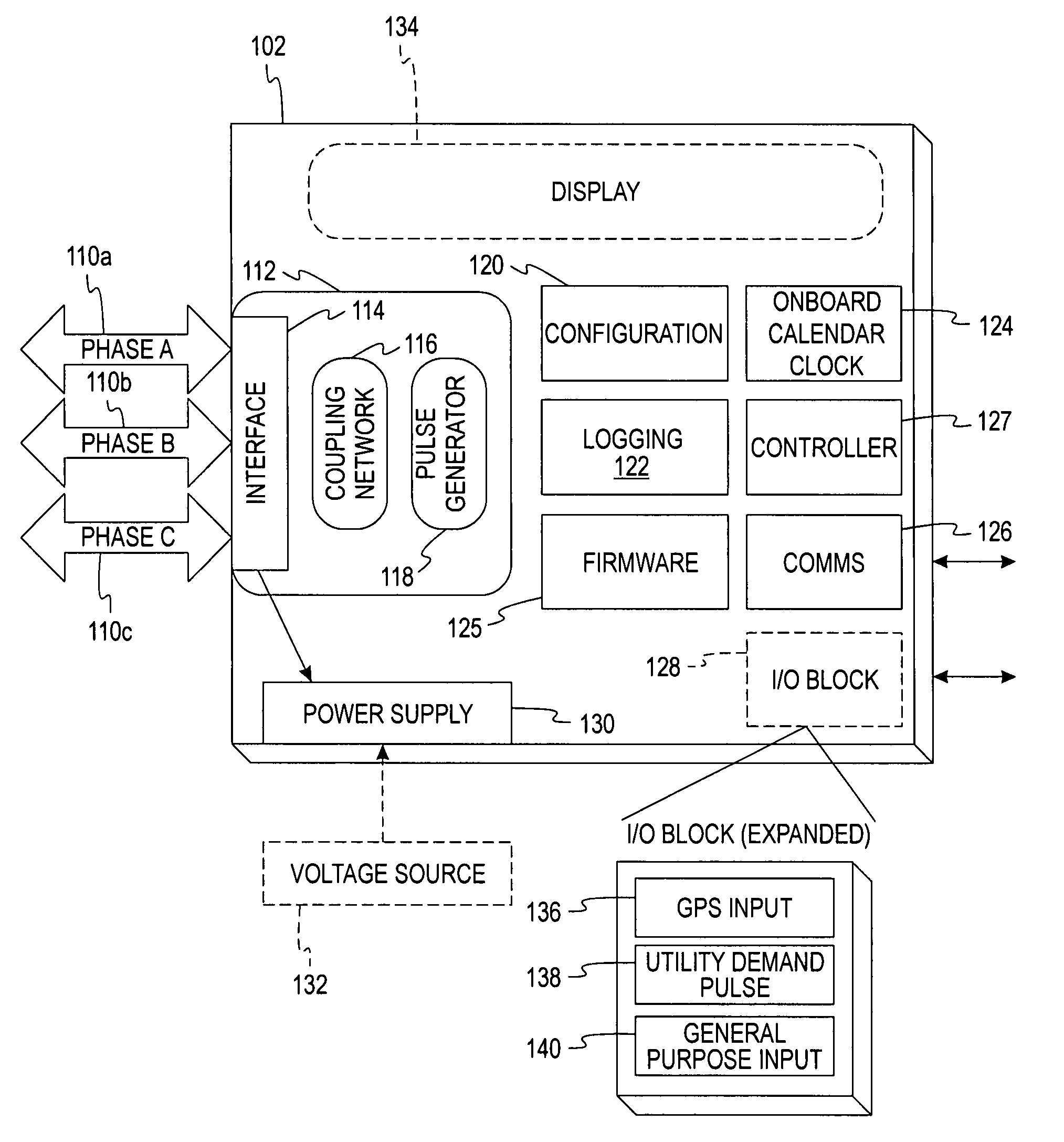
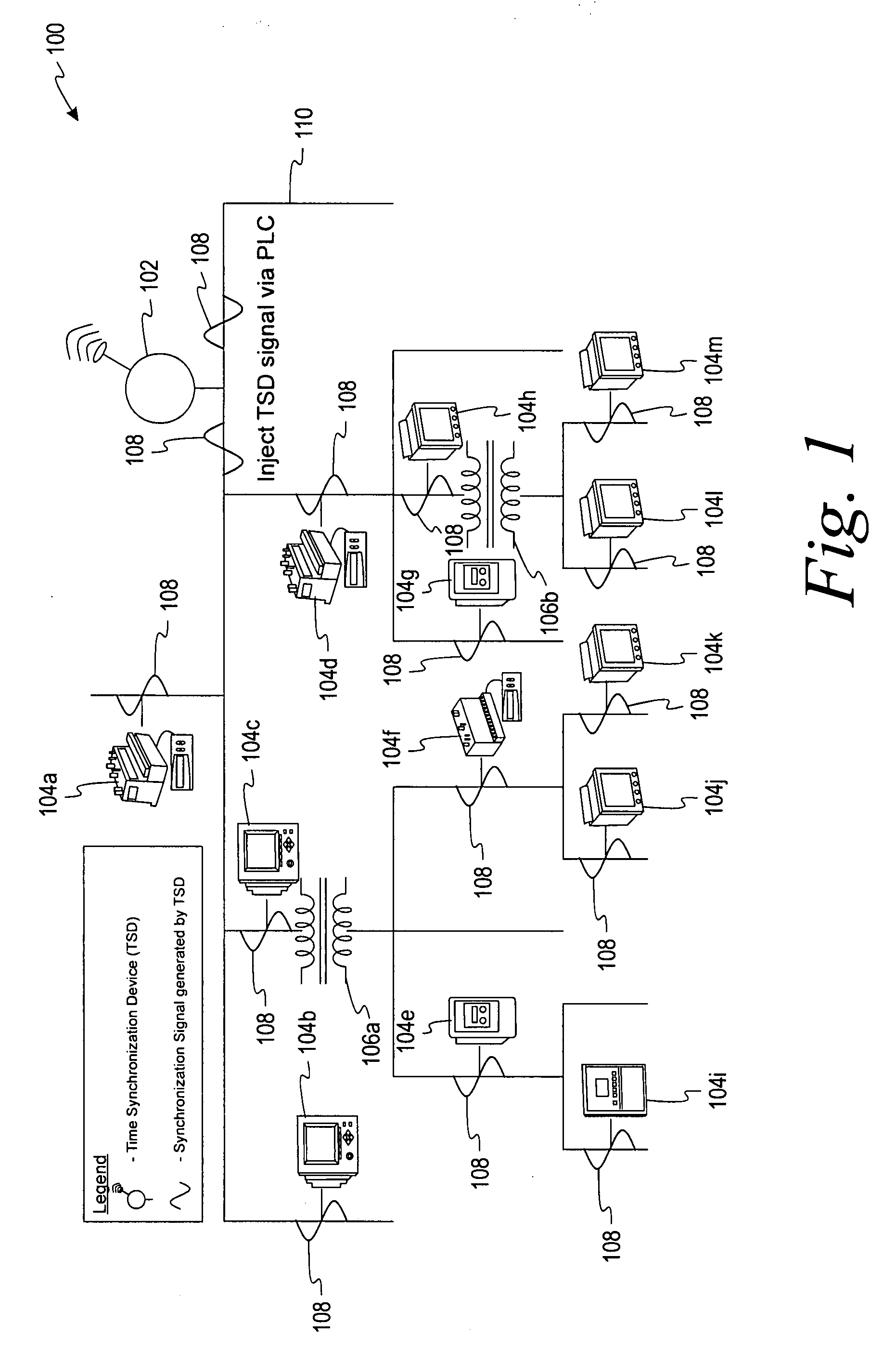
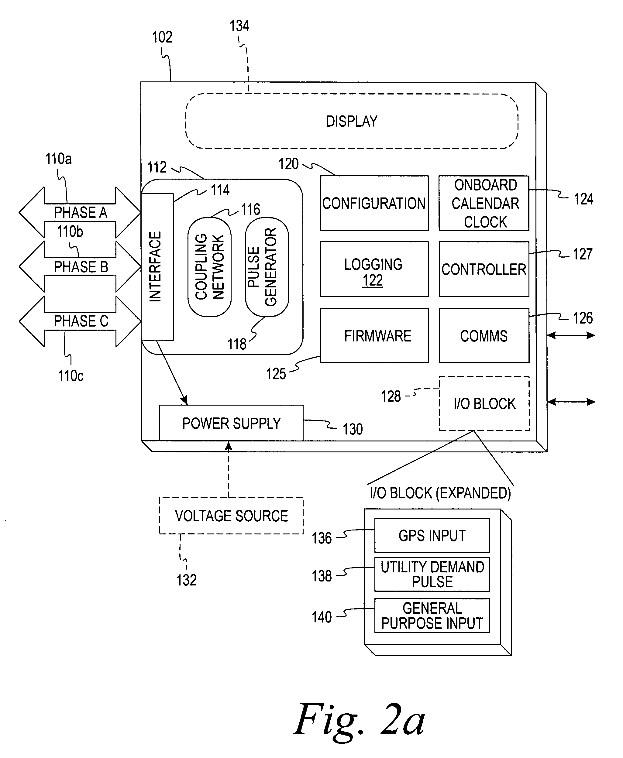
[0023]Aspects of the present invention not only enhance existing data alignment capabilities in meters, but also implement time-keeping / time-stamping on metering devices that lack an on-board clock. Furthermore, aspects of this invention provide a method of time-keeping / time-stamping for monitoring devices that lack an on-board clock. Aspects of the present invention allow monitoring devices of varying capabilities to all be aligned to a common time reference. For example, some monitoring devices may lack both external communications capability and an on-board clock. Other monitoring devices may have one or both such capabilities. A monitoring device is a device having the ability to sample, collect, or measure the operational characteristics of a utility system.

[0024]An important aspect of the present invention is a novel time synchronization device, or “TSD,” which in general, couples onto the power distribution conductors a synchronization signal (also referred to herein as a “TS...


PUM


Abstract

A time synchronization device (TSD) that produces a synchronization signal and couples it onto energized power conductors in a power monitoring system. Monitoring devices coupled to the TSD include frequency detection algorithms, such as a Goertzel filter, for detecting the synchronization signal and interpreting the information encoded in the signal. The frequency of the synchronization signal may correspond to the fourth or tenth harmonic component of the fundamental frequency of the voltage on the power conductors. The magnitude of the signal is selected to be above the expected or established noise floor of the power monitoring system plus a predetermined threshold. The duration of the signal can be varied, such as lasting a full cycle of the fundamental frequency. Multiple TSD signals received in a predetermined sequence may be converted into digital words that convey time, configuration, reset, control, or other information to the monitoring device.

Description

FIELD OF THE INVENTION[0001]The present invention relates generally to utility systems, and, in particular, to a method and apparatus for synchronizing data in a utility system.BACKGROUND OF THE INVENTION[0002]Data acquisition from an electrical power system helps and operator understand how energy is being consumed by the power system. However, measured data is scalar without the context of when the measured data was actually captured. Ideally, time would be uniform and fixed across the power system, but time is not homogeneous in practical applications. Time is a relative concept that is subject to different variables such as the location, accuracy, and precision of a clock. Because of these and other intrinsic complications, a simple timestamp is often insufficient to precisely describe the temporal moment when a given data point was captured. This problem becomes readily apparent in power monitoring systems, especially as more monitoring devices are incorporated into the power s...

Claims


Application Information

Patent Timeline
Patent Type & Authority Applications(United States)
IPC IPC(8): H04L7/00
CPCG01D4/002H04B3/542H04B2203/5433H04B2203/5458H04B2203/5466H04B2203/5483Y04S20/36Y04S20/48Y02B90/241Y04S20/32G01D2204/22G01D2204/47Y02B90/20Y04S20/30
Inventor BICKEL, JON A.ASHBY, E. AVERY
Owner SCHNEIDER ELECTRIC USA INC
Why Eureka
Try Eureka