Transmitter, Receiver, Communication System, Communication Method, Communication Program

a technology for applied in the field of transmitting devices and receivers, communication systems, communication methods, communication programs, can solve the problems of increasing communication overhead, increasing communication overhead, and reducing communication speed, and achieve the effect of quick connection

Active Publication Date: 2008-11-13
SHARP KK
View PDF77 Cites 45 Cited by
  • Summary
  • Abstract
  • Description
  • Claims
  • Application Information

AI Technical Summary

Benefits of technology

[0040]An object of the present invention is to provide a transmitter, receiver, communication system, communication method, communication program, which allow quick establishment of connection.

Problems solved by technology

In spite of the flexibility for realizing various applications, those rigorous communication layers are defined through a complicated procedure, thereby increasing the overhead required for communication.
The complicated procedure, which results from rigorous separation of layers, particularly causes an increase of communication overhead.
Moreover, though the confirmation of retransmission for each packet helps to increase communication reliability, it also decreases communication speed.
The connection overhead can be ignored in a long time communication, but it becomes a serious problem if the data is transferred in a short time.
The rigorous retransmission also decreases communication efficiency.
Also, because of the transmission of plural XID commands, unreliability for immediate response, and the 500 ms blank period after 2 to 16 XID commands are sent, transmission / reception of the XID command and the XID response takes a longer time.
However, due to the characteristics of light, when the infrared interface between the communication devices exceeds a certain angle (±15 in IrDA standard) or exceeds a certain distance (20 cm or 1 m in IrDA), the communication fails in process of transmission even when a highly reliable communication method is employed.
This is because search for station and information exchange takes some time in the IrDA transmission, requiring frequent confirmation of data transmission / reception between the transmitter and the reception device, thereby decreasing transfer efficiency.
As a result, the communication is more likely to fail in process of transmission.
For example, Japanese Laid-Open Patent Application Tokukai 2004-509527 (published on Mar. 25, 2004) discloses a method of transferring a file from one device to another via wireless communication so as to displaying the file in a device in the receiving end, but the same problem occurs when infrared light is used.

Method used


Image

  • Transmitter, Receiver, Communication System, Communication Method, Communication Program
  • Transmitter, Receiver, Communication System, Communication Method, Communication Program
  • Transmitter, Receiver, Communication System, Communication Method, Communication Program

Examples


first embodiment

[0134]One embodiment of the present invention will be described below with reference to FIGS. 1 through 9.

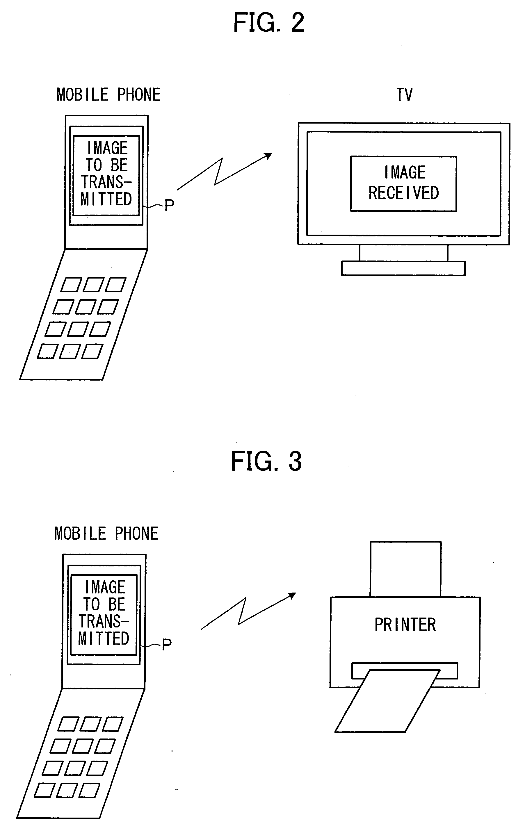
[0135]As shown in FIG. 2, a data transfer system according to the present invention is constituted of a mobile device, such as a mobile phone; and an electronic device, such as a display device. In this system, an arbitrary file stored in a storage medium of the mobile device is selected, and is transmitted to an infrared interface of the electronic device, allowing the electronic device to fetch the data. The arbitrary file may be an image file, image data, broadcast information, or document data (hereinafter simply referred to as “data”). Note that, the electronic device is not limited to a display device, but may be an printing device shown in FIG. 3; a recording device shown in FIG. 4 such as a DVD (Digital Video Disk) recorder, a CD (Compact Disk) recorder, a HDD (Hard Disk Drive: Hard Disk) recorder, or a VCR; other mobile devices shown in FIG. 5; or a personal computer sh...

second embodiment

[0220]The following explains another embodiment of the present invention with reference to FIGS. 10 and 11. Note that, the structure of the present invention is identical to that of First Embodiment except for the differences explained below. For ease of explanation, materials having the equivalent functions as those shown in the drawings pertaining to the foregoing First Embodiment will be given the same reference symbols, and explanation thereof will be omitted here.

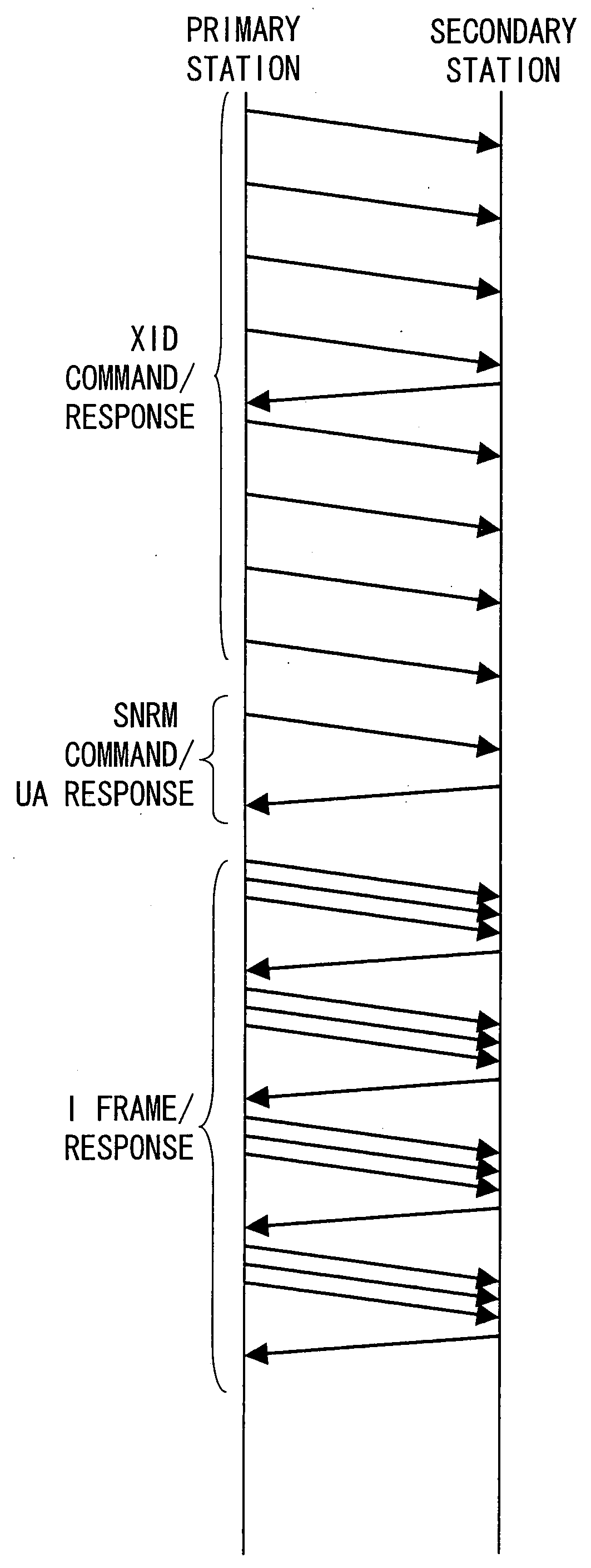
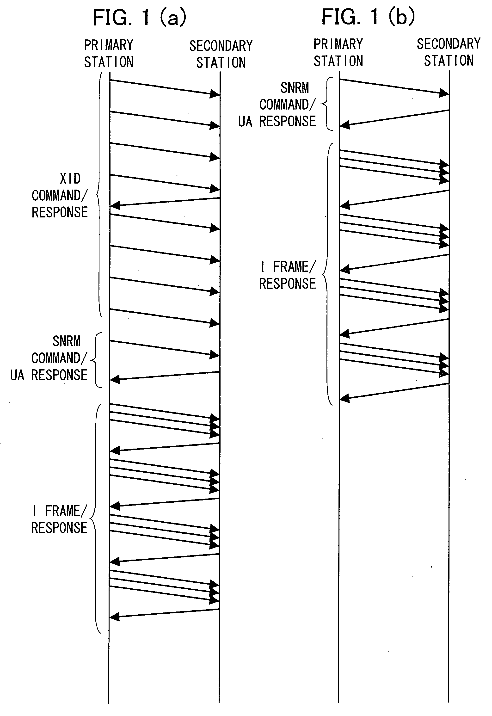
[0221]FIG. 10(b) shows an example using less number of connection processes so as to reduce the responses from the receiving end. Further, by carrying out one-way communication according to the communication function 8, the receiver does not need to have transmission function. Though such a one-way communication is not convenient in the general data communication because there is no way to confirm data reception, the present invention is free from this problem since the user can confirm the result of transmission of a ...

third embodiment

[0223]The following explains another embodiment of the present invention with reference to FIGS. 34 through 58. Note that, the structure of the present invention is identical to that of First and Second Embodiments except for the differences explained below. For ease of explanation, materials having the equivalent functions as those shown in the drawings pertaining to the foregoing First or Second Embodiment will be given the same reference symbols, and explanation thereof will be omitted here.

[0224](1) Communication Layer

[0225]FIG. 34 is a schematic view showing a corresponding relation among an OSI7 hierarchical model, IrDA hierarchical model and the hierarchical model of the communication system according to the present invention.

[0226]The present embodiment describes structure and operation of a transmitter and a receiver of the communication system according to the present invention, based on the OSI7 hierarchical model. The OSI7 hierarchical model is also refereed to as “OSI b...


PUM


Abstract

A communication system includes a transmitter and a receiver that establish mutual connections of a plurality of their communication layers for communication. The transmitter has a request generating part for generating a connection request including data and commands required to connect the plurality of adjacent communication layers, and a request transmitting part for transmitting the connection request to the receiver. The receiver has a request receiving part for receiving the connection request from the transmitter, and a connection establishing pant for extracting the data and commands from the connection request and establishing, based on the extracted data and commands, the connections of the communication layers. In this way, the time required for establishing the connections can be shortened. Thus, even if a data exchange is interrupted, a reconnection can be made in a short time to resume the data exchange.

Description

TECHNICAL FIELD[0001]The present invention relates to a transmitter and a receiver which establish connection to carry out wired / wireless communication. The present invention also relates to a communication system, a communication method, and a communication program.BACKGROUND ART[0002]In recent years, picture quality of CCD (Charge Coupled Device), which is used in various mobile devices including a mobile phone, a digital camera, a digital video camera, and a PDA (Personal Digital Assistant), has increased, allowing easy image pick-up of digital image with high quality.[0003]The image taken by a CCD is often stored in a storage medium, so as to be sent as an attachment file of an e-mail, transmitted as an image file via wired / wireless communication to be displayed in a different device, or printed on a paper to be handed from one to another. In this way, the image is used as shared data.[0004]Wireless communication, particularly one using infrared light, is often used for data tra...

Claims


Application Information

Patent Timeline
Patent Type & Authority Applications(United States)
IPC IPC(8): H04B10/00H04B10/04H04B10/06H04L29/06H04W76/02
CPCH04L12/2834H04L2012/2841H04L2012/2849H04W76/02H04L67/14H04L69/32H04W76/10H04M11/00
Inventor NAOE, HITOSHIFUKAE, FUMIHIROSAKAI, KOJIOHSAWA, SHOHEI
Owner SHARP KK
Why Eureka
Try Eureka